8
2
PANEL DESCRIPTION
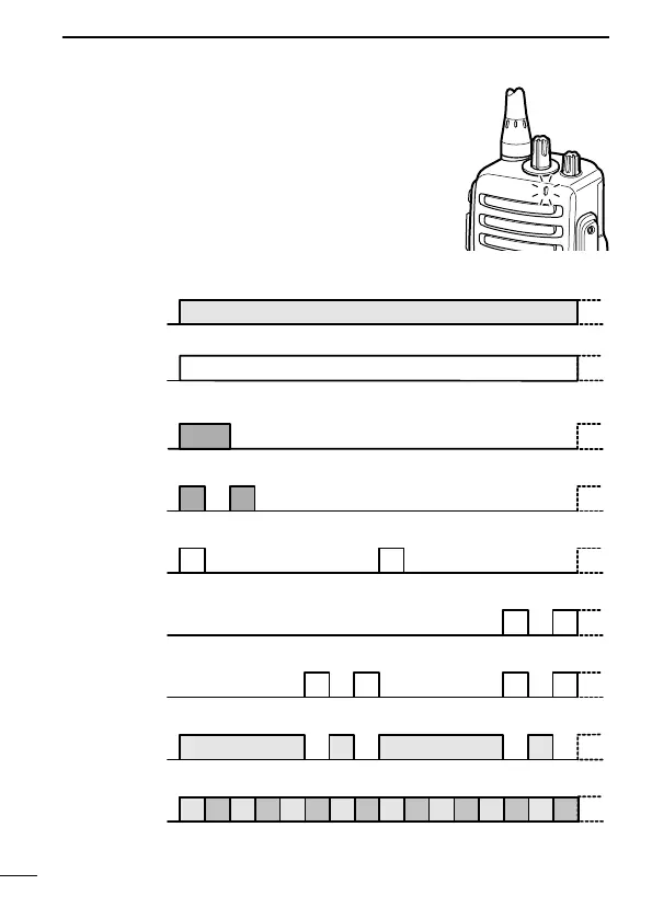
■ LED indicator
The LED indicator indicates several informa-
tion as follows;
(Ref.; R=Red, G=Green, O=Orange)
R R R R
O O
O O
G G G G
G G
G G G G G G G G
R G R G R G R G R G R G R G R G
R O R O R O R O R O R O R O R O
G
G G
Clone Er r
Clone TX/RX
Low BATT1
Low BATT2
Busy
F/S Scan
Call LED B link
Call LED O N
TX Low B ATT2
R
TX
• TX: Turns Red while transmitting a signal.
• RX: Turns Green while receiving a signal.
• Call LED (ON): When receiving a matched 2/5-tone.
• Call LED (Blink): When receiving a matched 2/5-tone.
• Fast/Slow scan: Blinks while Fast/Slow scan is activated.
• Low BATT1: You should charge the battery. (blinks slowly)
• Low BATT2: You must charge the battery. (blinks fast)
• TX low BATT2: Low BATT2 was detected during TX mode.
• CH err: Non-programmed channel is selected.

 Loading...