5 - 5
CPU5V
regurator
+5V
regurator
S5V
regurator
T5V
regurator
R5V
regurator
Power switch
R315
F701
(PA unit )
Q26–Q28
IC17
Q23
Q24, Q49
Q25
VCC
CPU5
CPU
+5V
S5V
“S5C”
“PWON”
Voltage line
Control signal
8
22
87
88
“T5C”
“R5C”
T5V
LED backlight driver (Q45),
LCD driver (IC20),
D/A converter (IC12), etc.
CPU (IC22),
EEPROM (IC10),
Reset IC (IC8), etc.
Drive amplifier (Q702),
Power amplifier (Q701), etc.
PLL IC (IC2),
VCO’s, etc.
Transmit circuits
Receive circuits
R5V
(IC22)
Battery pack
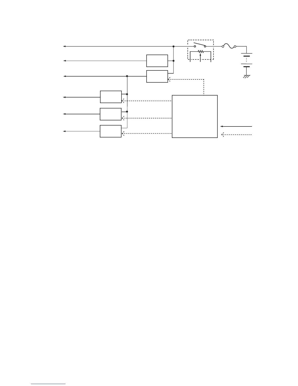
5-4 POWER SUPPLY CIRCUITS
Voltage from the attached battery pack is routed to whole of the circuit in the transceiver via a switch and regulators.
 Loading...