4-4 DSC CRICUITS
The DSC circuits monitors the DSC channel CH70 (156.525 MHz)
during stand-by.
4-4-1 RF CIRCUITS (MAIN UNIT)
The divided signals (DSC channel) are from the divider (L35,
C151, C152) are applied to the RF amplifier (Q61). The
amplified received signals are passed through the BPF (L62,
L63, C511, C512, C514−C516) to extract a 156.525 MHz
(CH70) signal. The filtered signals are then applied to the
double balanced 1st mixer (D39, L55, L56), and converted into
the 31.05 MHz 1st IF signal by being mixed with the 1st local
oscillator (LO) signals from the VCO (Q4, Q5, D1, D3).
4-4-2 1st IF CIRUIT (MAIN UNIT)
The converted 1st IF signal is applied to the 1st IF amplifier
(Q58, Q59), and the amplified 1st IF signal is passed through
a pair of crystal filters (FI4A, B). The filtered 1st IF signal is
amplified by another IF amplifier (Q63), and is then applied to
the FM IF IC (IC14, pin 16).
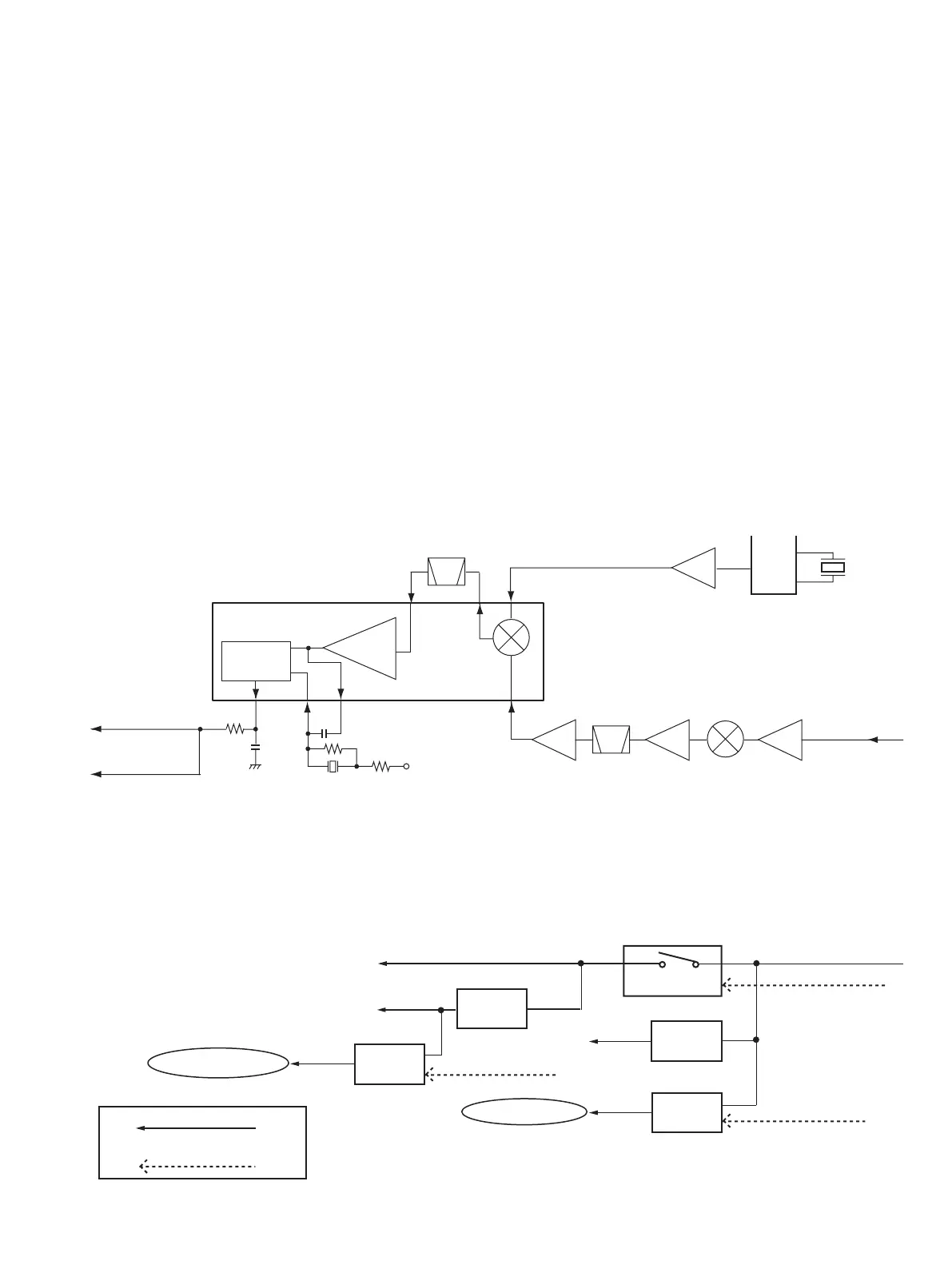
4-4-3 2nd IF AND DEMODULATOR CIRCUITS (MAIN UNIT)
The 1st IF signal from the 1st IF circuits is applied to the 450 kHz
2nd IF mixer in the FM IF IC (IC14, pin 16) and converted into
the 2nd IF signal by being mixed with the 30.6 MHz 2nd LO
signal from the PLL IC (IC1, pin 17) via the boubler (Q64).
The converted 2nd IF signal is output from pin 3, and
passed through the 2nd IF filter (FI6) to suppress sideband
noise. The filtered 2nd IF signal is applied to the limiter
amplifier (IC14, pin 5). The amplified 2nd IF signal is
FM-demodulated at the quadrature detector (IC14, pins 10,
11, X4) and output from pin 9. The demodulated signals are
applied to the DSC filters (AF UNIT; IC12) and AF circuits.
4-4-4 DSC DECODE (AF UNIT)
The demodulated signals from FM IF IC (MAIN UNIT; IC14,
pin 9) are filtered at the LPF (IC12, pins 1, 3) and HPF (IC12,
pins 5, 7) to extract the DSC signal. The filtered signals are
applied to the DSC decoder IC (IC15, pin 2). The decoded
DSC signal is output from pin 7, then applied to the CPU
(LOGIC BOARD; IC1, pin 17) to control the transceiver
according to the received DSC call content.
4-4-5 DSC ENCODE (LOGIC BOARD)
The DSC signal is generated by the CPU (IC1) and output
from pin 1, and applied to the modulation signal line via the
buffer amplifier (IC2, pins 5, 7). The DSC signal is filtered at
the LPF (AF UNIT; IC8, pins 1, 3), level-adjusted by R327
(MAIN UNIT), then applied to the modulation circuit (MAIN
UNIT; D2).
4 - 4
0OWERCONTROLLER
11
(6
6##
,6
2EGURATOR
)#
,6
#05)#
36
2EGURATOR
36
6OLTAGELINE
#ONTROLSIGNALFROMTHE#05)#
h3%.$vFROMPIN
h2#6vFROMPIN
h072/.vFROMPIN
&ROMTHEPOWERSUPPLY
46
#ONTROLLER
11
46
26
2EGURATOR
11
)#
26
2ECEIVECIRCUITS
4RANSMITTERCIRCUITS
!&POWERAMPLIFIERFOREXTSPEAKER!&5.)4)#
$3#ENCODINGBUFFER,/')#"/!2$)#ETC
,#$DIMMERCONTROLLER,/')#"/!2$11
$3#DECODER!&5.)4)#ETC
4-5 POWER SUPPLY CIRCUITS (MAIN UNIT)
Voltage from the connected power supply is routed to whole of the circuit in the transceiver via switches and regulators.
Q64
30.6 MHz 2nd LO signal
PLL IC
(IC1)
×2
Q63
1st IF
Q58, Q59 D39
1st IF
Q61
Received signals
from the divider
(L35, C151, C152)
RF
Mixer
Quadrature
detector
16
R10V
X4
1110
FM IF IC (IC14)
Limiter
amp.
to the AF circuits
• 2nd IF AND DEMODULATOR CIRCUITS (CH70 RX)
9
2
17
35
to the DSC filters
(AF UNIT; IC12)
X1
15.3 MHz
15
16
FI6
FI4
 Loading...