5 - 1
5-1 PREPARATION
The receiver (IC-R2) must be adjusted on the adjustment mode after programmed adjustment frequency data into memory chan-
nel. When you program adjustment frequency data into memory channel, optional CS-R2 PROGRAMMING SOFTWARE, OPC-478
CLONING CABLE are requird.
‘‘
REQUIRED TEST EQUIPMENT
‘‘
SOFTWARE INSTALLATION
NOTE: Before using the program, make a backup copy of the original disk. After making a backup copy, keep the original disk
in a safe place.
q Boot up DOS.
w Insert the backup disk into the floppy drive A.
e Type the following to install the adjustment program:
A:\>
INSTALL A C:\CSR2 [Enter]
‘‘
ADJUSTMENT FREQUENCY DATA
When program adjustment frequency data (at right) into memory
channel, back up the original memory data using the optional CS-
R2, OPC-478, and re-program it after adjustment.
CAUTION: When clone the adjustment frequency data to the
receiver, the receiver’s memory channel wiil be over-
written the data and deleted original memory data at
same time.
‘‘
ENTERING THE ADJUSTMENT MODE
q Connect a JIG (see illustration at CONNECTION) to the [SP]
jack.
w Push and hold [FUNC], then turn power ON.
e Disconnect the JIG and connect a PC with an OPC-478.
r Boot up DOS.
t Type the following to start up the adjustment program:
C:\>
CD CSR2 [Enter]
C:\CSR2>CSR2 [Enter]
• Main menu appears at the top side of the cloning program,
select the sub-menu “Screen”–“Memory CH”–“Bank 1”, then
input adjustment frequency (at right).
y Select “Write –> Receiver” of the Clone on the top menu.
• Application writes adjustment frequency data to the connected receiver.
u Disconnect the cloning cable and turn power OFF, then turn power ON to start adjustment.
‘‘
OPERATING ON THE ADJUSTMENT MODE
Change the value : [DIAL]
Change the channel [UP] : [BAND]
Change the channel [DOWN] : [BAND]
‘‘
EXITING THE ADJUSTMENT MODE
When the adjustment is finished, the receiver must be cancelled adjustment mode to use normal operation, otherwise receiver
does not work properly.
q Turn power OFF.
w Push and hold [FUNC] and [V/M], then turn power ON.
NOTE: All memory data except adjustment value will be cleared at this operation.
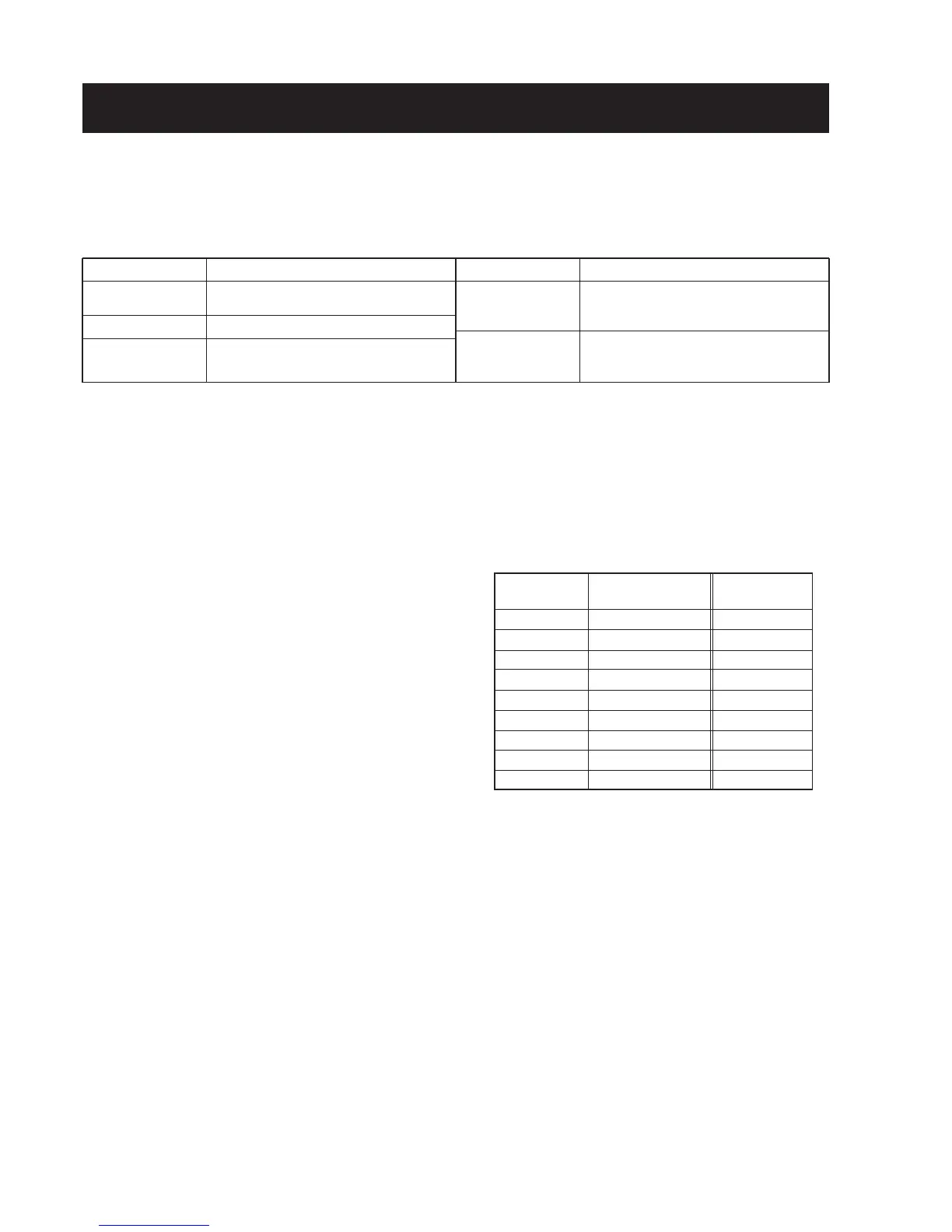
EQUIPMENT
DC power supply
AC millivoltmeter
External speaker
GRADE AND RANGE
Output voltage : 3.0 V DC
Current capacity : 1 A or more
Measuring range : 10 mV–10 V
Input impedance : 8 Ω
Capacity : 1 W or more
EQUIPMENT
Frequency counter
Standard signal
generator (SSG)
GRADE AND RANGE
Frequency range : 0.1–600 MHz
Frequency accuracy : ±1 ppm or better
Sensitivity : 100 mV or better
Frequency range : 0.1–1300 MHz
Output level : 0.1 µV–32 mV
(–127 to –17 dBm)
• ADJUSTMENT FREQUENCY
NOTE: Adjustment frequency data must be pro-
grammed into proper channels, don’t turn the
order of channels, otherwise adjustment value
will be wrong.
SECTION 5 ADJUSTMENT PROCEDURES
Channel Frequency Display ch.
No. [MHz] No.
0 280.100 FR
1 145.600 tk
2 435.600 tk
3 14.100 RS
4 145.100 RS
5 200.100 RS
6 435.100 RS
7 650.100 RS
8 1100.100 RS
 Loading...