30
Concord CXi - Installation
42
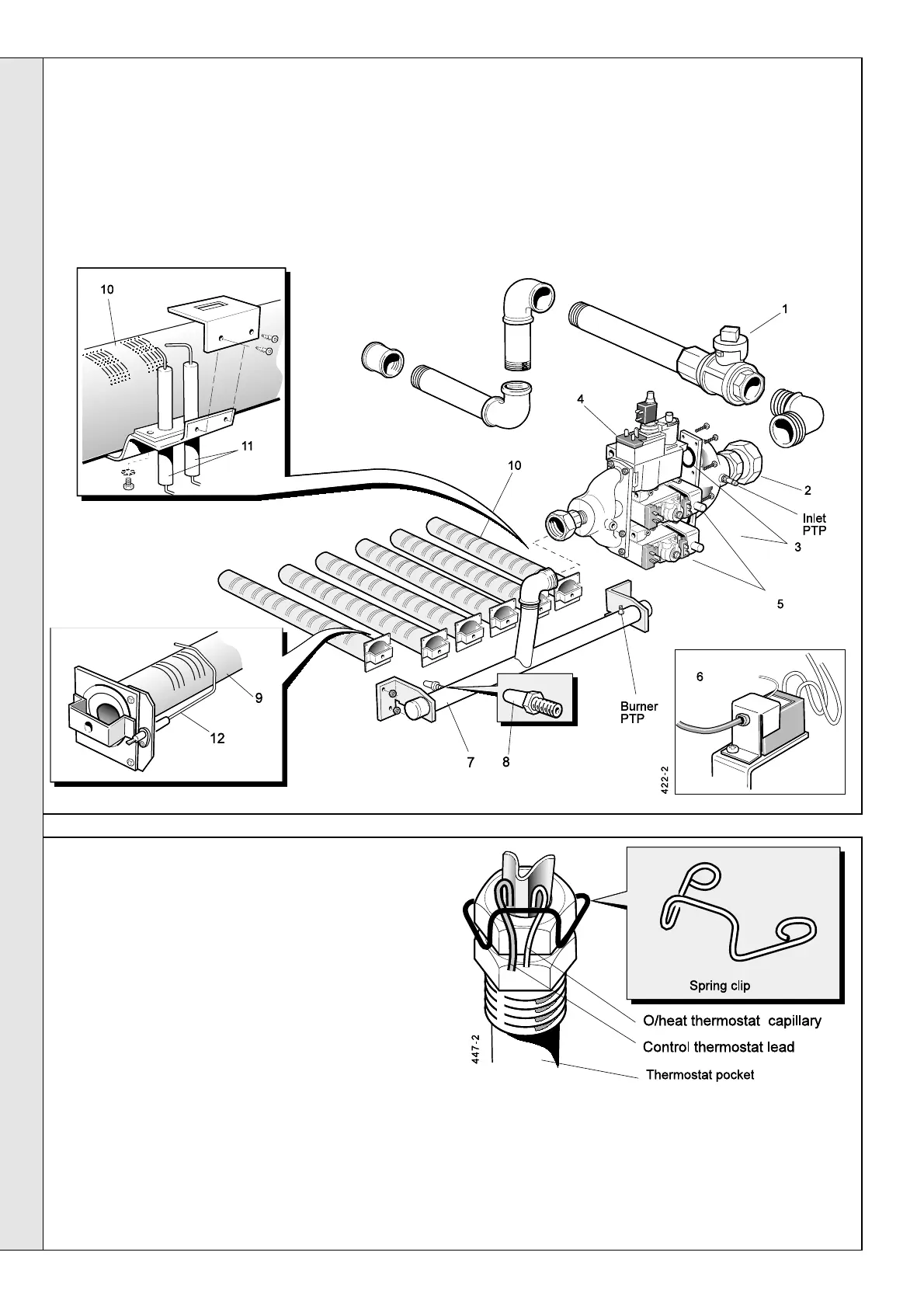
BURNER AND CONTROLS ASSEMBLY - Exploded view - CXi 180
1. Pull out the spring clip in the thermostat pocket in
the flow header and pull out the overheat
thermostat phial and capillary.
2. Ensure that the electrical supply is switched OFF.
3. Lift off the jacket front panel and top panel.
4. Unclip the capillary from it’s clips on the jacket
side panel.
5. Undo the 2 screws securing the overheat
thermostat assembly and withdraw the assembly.
6. Undo the 2 screws securing the thermostat cover
to the support bracket and withdraw the
thermostat from the cover.
7. Remove the push on terminals from the
thermostat body noting their positions.
SERVICING
SERVICING
LEGEND
1. Main gas inlet cock.
2. Gas inlet union.
3. 'O' ring seal.
4. Gas control valve.
5. Gas control valve.
43
OVERHEAT THERMOSTAT
6. Spark generator.
7. Burner manifold.
8. Main injector.
9. Main burner.
10. Main burner (RH).
11. Ignition electrodes.
12. Detection electrode assembly.
PTP Pressure test point.
8. Fit the new thermostat in reverse order (ensuring that the
capillary is located in the notch provided in the support
bracket ). Reconnect the push on terminals to thermostat
terminals 1, 2 and earth .
Ensure that the thermostat capillary is re routed through the
jacket side panel clips and that the phial is secure in the
pocket fitted to the flow header using the spring clip.
 Loading...