56
SERVICING SCHEDULE
To ensure the continued safe and efcient operation of the
appliance it is recommended that it is checked at regular
intervals and serviced as necessary. The frequency of
servicing will depend upon the installation condition and
usage but should be carried out at least annually.
Ideal Boilers does not accept any liability resulting from
the use of unauthorised parts or the repair and servicing
of appliances not carried out in accordance with the
Company’s recommendations and specications.
Note.
Some aluminium oxide build-up within the heat exchanger
assembly is quite usual with this type of condensing boiler.
Though removal and cleaning is recommended annually,
the heat exchanger, sump and condensate trap must
be inspected and cleaned after a maximum of 2 years
operation.
1. Light the boiler and carry out function checks, noting
any operational faults.
2. Run the boiler for 5 minutes and then check the gas
consumption rate. Refer to procedure opposite on how
to force the burner to maximum rate.
3. Optional test - Connect a suitable gas analyser to the
sampling point tted in the ue adapter. For correct
boiler operation the CO/CO
2
ratio of the ue gas should
not be greater than 0.004 ratio and the CO
2
values
should match those in table 1. If this is the case and
the gas input is at least 90% of the nominal, once
compliance with the note above is ensured, then no
further action need be taken. If not proceed to 4.
4. Remove and clean the burner. Refer to Frames 59 and
60.
5. Inspect the heat exchanger through the burner opening.
If there are signs of aluminium oxide build up, spray
water down the ueways. Refer to Frame 60.
6. Remove the sump cover and scrape out any deposits.
Refer to Frame 61.
7. Remove the condensate trap and ush through with
water. Refer to Frame 62.
8. Check that the ue terminal is unobstructed and that the
ue system is sealed correctly.
9. After completion of servicing refer to Frame 55 for
reference to nal safety checks.
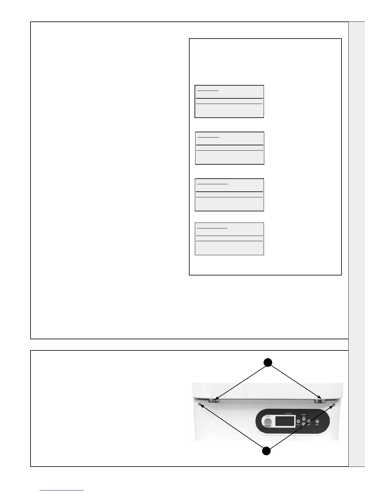
57
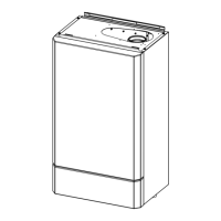
CASING REMOVAL
Front Panels
1. Pull the two sides of the control casing door to open.
2. Remove the two screws retaining the front panel, lift the panel
to remove.
3. Remove the two screws retaining the control panel and swing
the panel down into the service position.
Side Panels
Note. Removal is not required for normal service.
1. Remove the two (or three) screws from the top and bottom of
the side panels.
2. Re-assemble in reverse order.
2
3
SERVICING
Ideal 80kW
Normal Operation
Set Flow Temp’
Set DHW Temp’
Ideal 80kW
Set DHW Temp’
Set Off/Sum/Win
Out’ Sensor Slope
State of Inputs
Rotate KNOB clockwise until the following screen is displayed
Set Off/Sum/Win
Standby
Summer
Winter
Press - for more
Set Off/Sum/Win
Minimum
Maximum
Press - for more
Press SELECT and the following screen will be displayed
Press + and - until the followint screen is displayed.
Press ENTER and the boiler will go to Maximum Rate for 5 minutes
Operation will be automatically reset at the end of 5 minutes
SETTING TO MAXIMUM OUTPUT
Ensure that there is a current CH demand to the boiler (e.g. the
CH Switched Live is on)
Press SELECT and the following screen witll be displayed.
The kW output number in the 1st line will vary depending on the
maximum output of the boiler.
 Loading...