37
EXTERNAL ELECTRICAL CONTROLS
Wiring External to the Boiler
The fuse rating should be 3A.
Wiring external to the boiler MUST be in accordance with the current
I.E.E. (BS.7671) Wiring Regulations and any local regulations.
Difculty in wiring should not arise, providing the following directions
are observed:
1.
The appliance must be wired
with a permanent live supply.
External controls MUST NOT be wired in series with this mains
input.
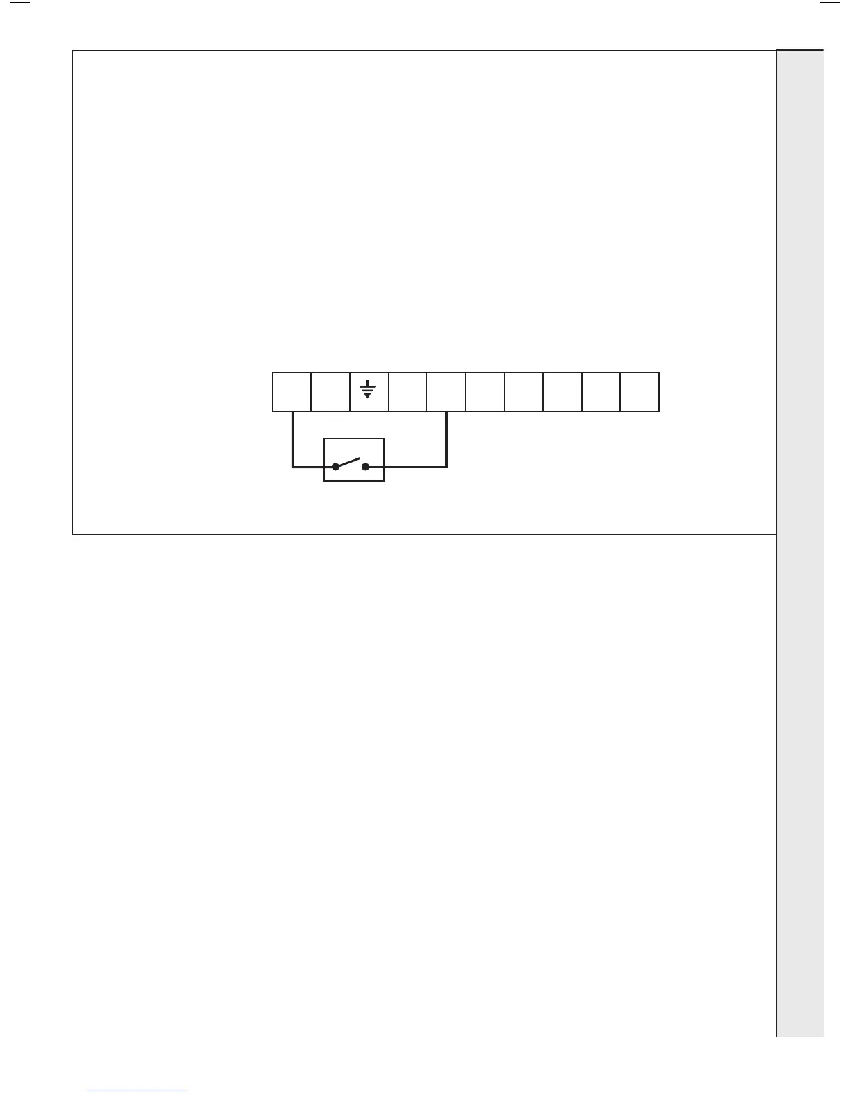
2. 230V AC output is provided and maybe if pump overrun is required
be used for the system pump. Care must be taken to ensure that
the earth conductor is longer than the current carrying conductors.
3G9503b
L N
CH
ON
HW
ON
R/S
ON
HW
OFF
C/S
ON
Earths are not shown for clarity but must
never be omitted.
Frost Protection
If parts of the pipework run outside the house or if the
boiler will be left off for more than a day or so then a
frost thermostat should be wired into the system.
The frost thermostat should be sited in a cold place but
where it can sense heat from the system.
Note. If the boiler is installed in a garage it may be
necessary to t a pipe thermostat, preferably on the
return pipework.
INSTALLATION
 Loading...


