INSTALLATION
25
INTERNAL WIRING
24
ELECTRICAL CONNECTIONS
Wiring should be 3 core PVC insulated cable, not less than
0.75mm
2
(24 x 0.2mm), and to BS 6500 Table 16. For IE
reference should be made to the current ETCI rules for electrical
installations.
Connection must be made in a way that allows complete
isolation of the electrical supply such as a double pole switch
having a 3mm (1/8”) contact separation in both poles. The
means of isolation must be accessible to the user after
installation.
WARNING. This appliance MUST be earthed.
A mains supply of 230Vac ~ 50 Hz is required.
The fuse rating should be 3A. All external controls and wiring
must be suitable for mains voltage.
Wiring external to the boiler MUST be in accordance with the
current I.E.E. (BS.7671) Wiring Regulations and any local
regulations.
FROST THERMOSTAT - WIRING
If parts of the system are
vulnerable to freezing or the
programmer is likely to be left off
during cold weather, a frost stat
should be tted in conjunction with
a pipe thermostat.
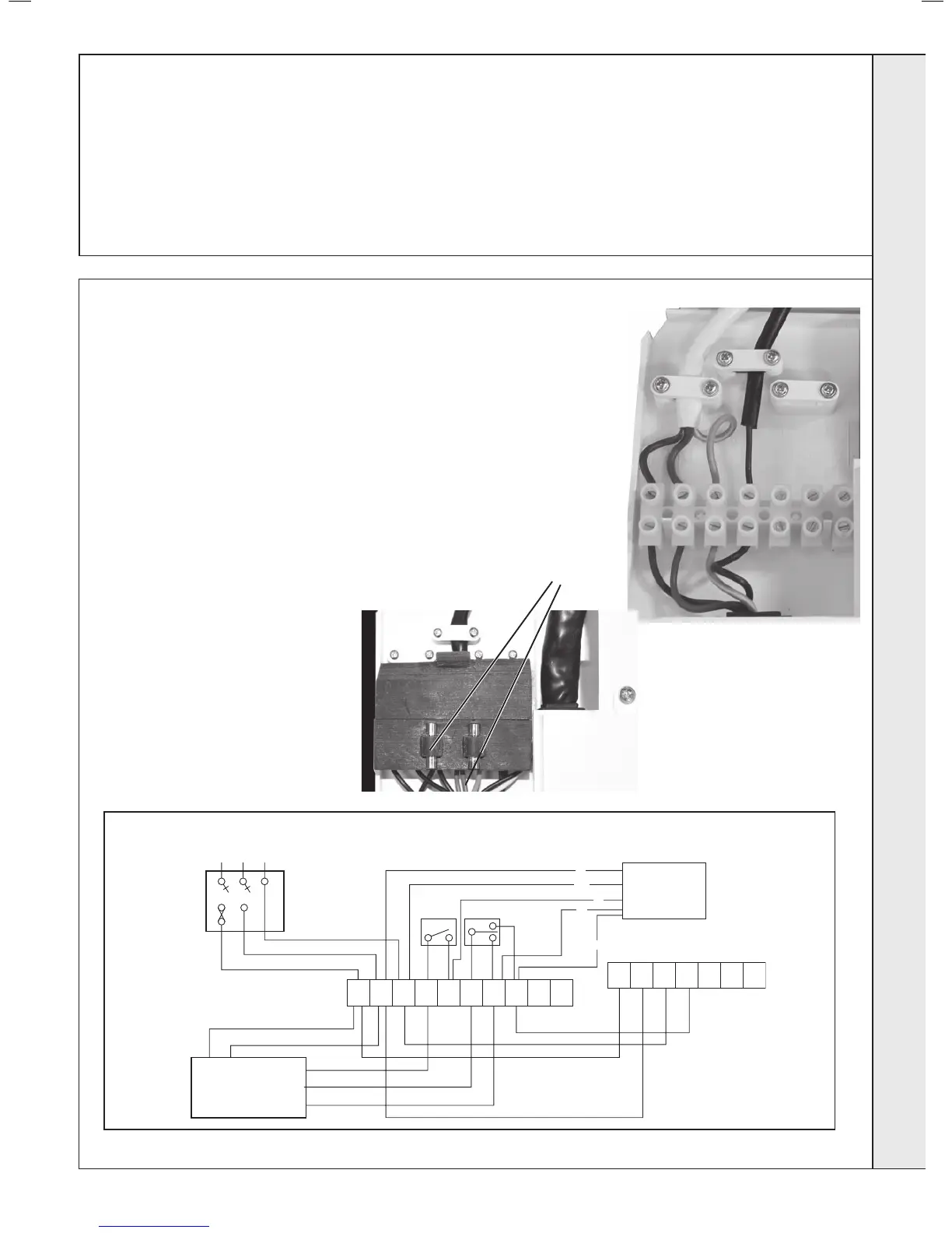
LOGIC + SYSTEM BOILER WITH Y PLAN SYSTEM
Spare PCB fuses
The Logic + System boiler comes pre-tted with 1.8m of mains cable. This must be
connected to a permanent live supply and NOT switched by thermostats/programmers.
If the supply cord is damaged, it must be replaced by the manufacturer, service agent or
similarly qualied persons in order to avoid hazard. For installers wishing to change this
cable refer to Frame 27.
The terminal block cover carries two spare fuses for the main PCB.
Connecting the Switched Live to the Boiler
1. Consult the Y Plan and S Plan diagrams below.
2. Isolate the mains supply to the boiler
3. Remove the front panel. Refer to Frame 8.
4. Swing the control box down into the servicing position.
5. Route incoming cable through a grommet in the bottom
panel (note that the grommets are “blind” and will require
puncturing) and secure using the clamp.
6. Connect the switched live to the terminal block as shown.
 Loading...


