Page 9
INCOMING COLD SUPPLY
M
DC
DC
DC
TO
EXTERNAL
TAP
SINK
WATER SOFTENER (IF NECESSARY)
WM or DWM
WHB
W.C.
DC
DC
SH
DHW
WHB
WC BATH
SCV
SCV
P&T
ERV/NRV
PRV
DCV
Note:
Cold supplies to single taps must be
taken from the mains cold water
system.
Cold supplies to mixer taps must be
taken from the balanced cold water
connection on the combination
valve.
General Restrictions
a. The highest hot or cold water draw o point should not exceed 10 metres above
the Pressure Reducing Valve.
b. An ascending spray type bidet or any other appliance with a Class 1 back-syphonage
risk requiring a type A air gap should not be used.
c. Ideal Pro should not be used where steam is the primary heating medium, or in a
situation where maintenance is likely to be neglected.
d. Unvented cylinders are not suitable for use with solid fuel boilers.
e. If the supply to the mixer ttings (other than a dual outlet type) is not taken from
the balanced supply the system will become over pressurized and cause the
pressure relief valve to discharge. Over time this could also cause the premature
failure of the appliance itself which will not be covered by the warranty.
f. In larger properties with a number of bathrooms/en-suites and long pipe runs
we would recommend that the balance cold supply is provided with its own
pressure reducing valve and is not taken from the balanced cold connection on
the combination valve. In this case it will also be necessary to t a small expansion
vessel on the balanced cold water system to accommodate the pressure rise caused
by the increase in temperature of the balanced cold water.
g. Check the performance requirements of the terminal ttings with regard to ow/
pressure are suitable.
h. In relation to potable water systems, expansion vessels shall be installed in a vertical
orientation and located so that the length of the connecting pipe work is kept to
a minimum.
Shower Fittings
Aerated taps are recommended to prevent splashing. Any type of shower mixing valve
can be used as long as both the hot and cold supplies are mains fed. However, all mains
pressure systems are subject to dynamic changes particularly when other hot and cold
taps/showers are opened and closed, which will cause changes in the water temperature
at mixed water outlets such as showers. For this reason and because these are now no
more expensive than a manual shower we strongly recommend the use of thermostatic
showers with this appliance. These must be used in 3 storey properties where the
impact on pressure/temperature of opening another tap in the system is greater than
normal. The shower head provided must also be suitable for mains pressure supplies.
Pipe Layout
In all mains pressure installations it is important
to remember that the incoming cold supply
must be shared between all terminal ttings. It
is important that a 22mm supply is brought to
the appliance and a 22mm take-o is continued
at least to the bath. If there are two baths, 28mm
pipework should be considered. One metre of
smaller diameter pipework, or ow restrictors,
should be provided on the nal connection to
all outlets so as to balance the water available.
In any event the distribution pipework should
generally be in accordance with BS EN806-1 to 5.
Plastic Pipework
This appliance is suitable for use with plastic
pipework as long as the material is recommended
for the purpose by the manufacturer and is installed
fully in accordance with their recommendations.
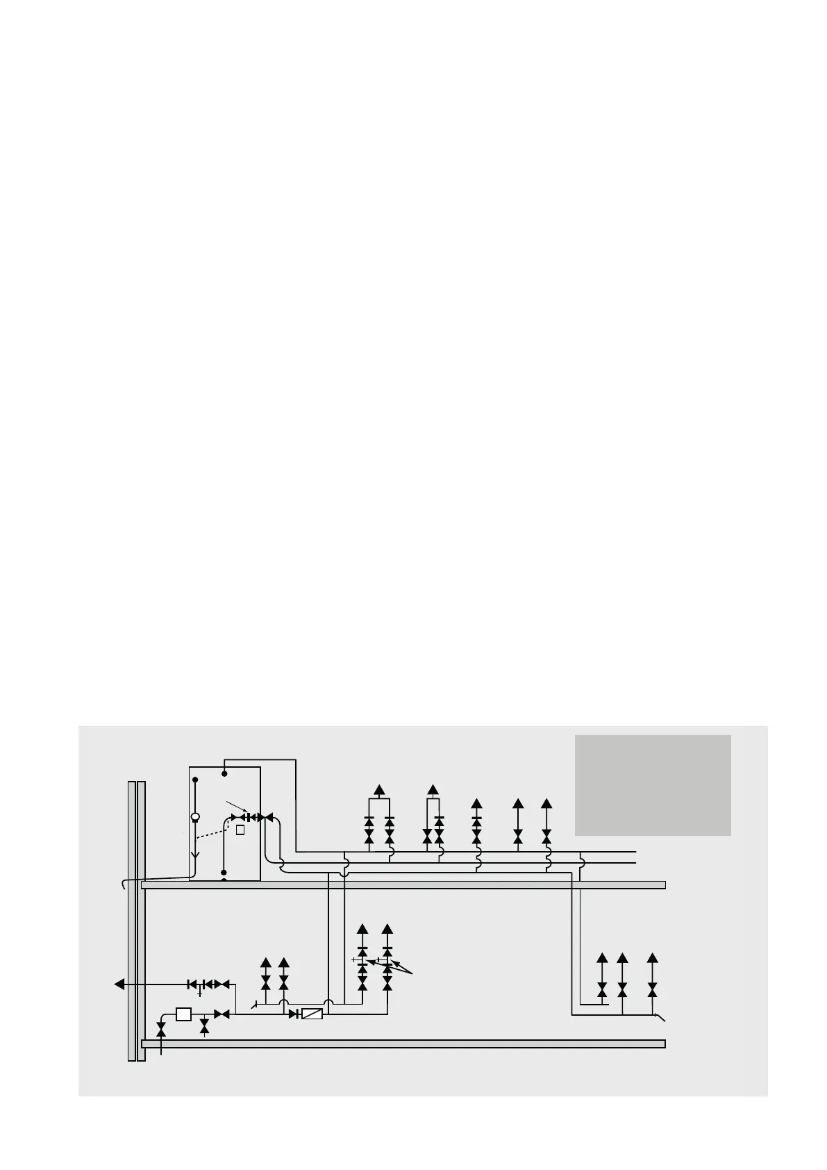
Secondary Hot Water Circulation
All models 210 litres and above are tted with
a secondary return tapping as standard (see
tables 1 and 2 for details). If tted, an extra
expansion vessel may be necessary. A non-
return valve MUST be FITTED near the return
connection. No valve or terminal tting should
be installed between the non return valve and
the cylinder. (See schematic arrangement on
page 15.) All pipes kept hot by the secondary
circulation should be insulated.
INSTALLATION
INSTALLATION

 Loading...