C82
1-27
1-28
C82
1-26
5
4
1
3
2
5
6
7
8
8
10
11
9
S
A
C82
12 - IE
INSTALLATORUSERMAINTENANCE
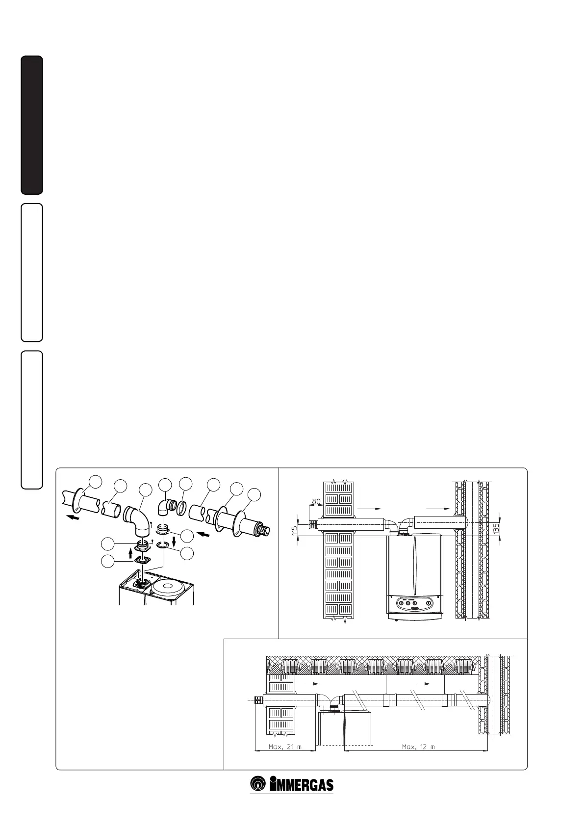
e kit includes (Fig. 1-28):
N°1 - Exhaust seal (1)
N°1 - Flange seal (2)
N°1 - Female intake ange (3)
N°1 - Female exhaust ange (4)
N°1 - 90° bend Ø 80 (5)
N°1 - Pipe closure cap (6)
N°1 - Intake terminal Ø 80 insulated (7)
N°2 - Internal rings (8)
N°1 - External ring (9)
N°1 - Exhaust pipe Ø 80 insulated (10)
N°1 - Concentric 90° curve Ø 80/125 (11)
female end (with lip seals) of the previously
installed element; this will ensure correct hold
and joining of the elements.
• Insulation of separator terminal kit. In case
of problems of fume condensate in the
exhaust pipes or on the outside of intake
pipes, Immergas supplies insulated intake and
exhaust pipes on request. Insulation may be
necessary on the exhaust pipe due to excessive
temperature loss of fumes during conveyance.
Insulation may be necessary on the intake pipe
as the air entering (if very cold) may cause the
outside of the pipe to fall below the dew point
of the environmental air. The figures (Fig.
1-27÷1-28) illustrate dierent applications of
insulated pipes.
Insulated pipes are formed of a Ø 80 internal
concentric pipe and a Ø 125 external pipe with
static air space. It is not technically possible
to start with both Ø 80 elbows insulated, as
clearances will not allow it. However starting
with an insulated elbow is possible by choosing
either the intake or exhaust pipe. When starting
with an insulated intake bend, it must be
inserted onto its ange up to the stop on the
fume exhaust ange, which will ensure that the
two intake and exhaust outlets are at the same
height.
• Temperature loss in insulated fume ducting.
To prevent problems of fume condensate in
the insulated exhaust pipe Ø 80, due to cooling
through the wall, the exhaust pipe length must
be limited to 12 metres. e gure (Fig. 1-28)
illustrates a typical insulation application in
which the intake pipe is short and the exhaust
pipe very long (over 5 m). e entire intake
pipe is insulated to prevent moist air in the
place where the boiler is installed, condensing
in contact with the pipe cooled by air entering
from the outside. The entire exhaust pipe,
except the elbow leaving the splitter, is insulated
to reduce heat loss from the pipe, thus
preventing the formation of fume condensate.
N.B.: When installing the insulated pipes, a
section clamp with pin must be installed every
2 metres.
• Conguration type B, open chamber and
forced draught.
By removing the lateral caps on the sealed
chamber and using the cover kit (optional) air
intake takes place directly from the environment
in which the boiler is installed and the fumes
are expelled in an individual ue or directly to
the outside.
The boiler in this configuration, following
the assembly instructions (Fig. 1-10÷1-11), is
classied as type B.
With this conguration:
- air intake takes place directly from the
environment in which the boiler is installed
and only functions in permanently ventilated
rooms;
- the fumes pipe must be connected to its own
individual ue or channelled directly into the
external atmosphere;
- type B open chamber boilers must not be
installed in places where commercial, artisan
or industrial activities take place, which use
products that may develop volatile vapours
or substances (e.g. acid vapours, glues, paints,
solvents, combustibles, etc.), as well as dusts
(e.g. dust deriving from the working of
wood, coal nes, cement, etc.), which may be
damaging for the components of the appliance
and jeopardise functioning.
When using type B installation conguration
indoors, it is compulsory to install the relative
upper cover kit along with the fumes discharge
kit.
The technical regulations in force must be
respected.
1.8 FUME EXHAUST TO FLUE/CHIMNEY.
Flue exhaust does not necessarily have to be connected
to a branched type traditional. Flue exhaust can be
connected to a special LAS type multiple flue.
Multiple and combine flues must be specially
designed according to the calculation method and
requirements of the standards, by professionally
qualied technical personnel. Chimney or ue
sections for connection of the exhaust pipe must
comply with standard requisites..
1.9 DUCTING OF EXISTING FLUES.
With a specic “ducting system” it is possible to reu-
se existing ues, chimneys and technical openings
to discharge the boiler fumes.. Ducting requires the
use of ducts declared to be suitable for the purpose
by the manufacturer, following the installation and
user instructions, provided by the manufacturer,
and the requirements of the standards.
1.10 FLUES, CHIMNEYS AND CHIMNEY
CAPS.
The flues, chimneys and chimney caps for the
evacuation of combustion products must be in
compliance with applicable standards.
Positioning the dra terminals. Dra terminals
must:
- be installed on external perimeter walls of the
building;
- be positioned according to the minimum
distances specied in current technical standards.
Fume exhaust of forced draught appliances
in closed open-top environments. In spaces
closed on all sides with open tops (ventilation pits,
courtyards etc.), direct fume exhaust is allowed for
natural or forced draught gas appliances with a
heating power range from 4 to 35 kW, provided the
conditions as per the current technical standards
are respected.
 Loading...