This document is a maintenance information manual for the Ingersoll Rand Air Percussive Rivet Buster, specifically for Models 9001 and 11001. It provides detailed instructions for disassembly, assembly, lubrication, and troubleshooting of the tool, ensuring proper operation and longevity.
Function Description:
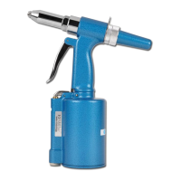
The Air Percussive Rivet Buster is a pneumatic tool designed for heavy-duty demolition and removal tasks, particularly for rivets. Its percussive action delivers powerful blows, making it effective for breaking, chipping, and driving applications. The manual focuses on the internal mechanisms that enable this percussive action, including the piston, valve box, and handle assembly, which control the airflow and impact force. The tool's design allows for the attachment of various accessories, enhancing its versatility for different tasks.
Important Technical Specifications (Inferred from Maintenance):
- Models Covered: 9001 and 11001.
- Power Source: Air (pneumatic).
- Lubrication: Requires Ingersoll Rand No. 10 Oil for internal parts.
- Torque Specification: Handle assembly to barrel connection requires 300 ft-lb (407 Nm) torque.
- Valve Lapping: Utilizes Grade 320 lapping compound for fitting the valve (14) into the valve box (12), ensuring a free fit.
- Dowel Pin Protrusion: The dowel pin (13) in the valve box should protrude 1/8" beyond the front face of the valve box cover.
- Air Port Cleaning: Air ports in the valve box should be cleaned with a 1/32" drill.
Usage Features:
- Accessory Retaining Mechanisms: The tool features different accessory retaining mechanisms depending on the model:
- Threaded Retainer (No. 9001-200): Involves an upper sleeve (23), accessory (26), lower sleeve (24), rubber bumper (25), retainer nut (22), lock spring (28), lock key (27), and lock pin (29). This system secures the accessory by threading the retainer nut onto the barrel and locking it with a pin and key.
- Plain-Type Retainer (No. 11001-18): Uses a lower sleeve (24), rubber bumper (25), retainer (30), and lock spring (31). This simpler mechanism secures the accessory by sliding the retainer onto the barrel and engaging a lock spring.
- Throttle Assembly: Controls the tool's operation, comprising a throttle lever (2), throttle lever pin (3), throttle valve assembly (4), throttle valve face (5), throttle face cap (6), throttle face cap nut (7), lock washer (8), throttle valve spring (9), and throttle valve cap (10). This assembly allows the user to initiate and stop the percussive action.
- Locking Mechanism: Includes an exhaust deflector (19), locking spring cover (16), locking ring (17), locking ring pin (18), and locking spring (15). This mechanism helps secure the tool's components and potentially prevents accidental disassembly during operation.
Maintenance Features:
- General Disassembly Guidelines:
- Disassemble only as far as necessary for repair.
- Use leather-covered or copper-covered vise jaws to protect parts from distortion, especially threaded members and housings.
- Avoid removing press-fit parts unless absolutely necessary.
- Ensure a complete set of new gaskets and O-rings are available before disassembly.
- Lubrication:
- Before final assembly, apply a thin film of oil to all parts.
- Apply O-ring lubricant to all O-rings.
- For routine lubrication, place approximately 3 cc of Ingersoll Rand No. 10 Oil into the air inlet and operate briefly to coat internal parts.
- Cleaning:
- Clean all parts thoroughly and wipe with a thin film of oil before installation.
- After disassembling the valve box, clean air ports with a 1/32" drill and wash the valve and valve box sections in a suitable solvent to remove all traces of lapping compound.
- For sluggish operation, flush the tool with a cleaning solution (3 cc into air inlet, operate for 30 seconds), followed by oil (3 cc into air inlet, operate for 5 seconds).
- Valve Box Assembly:
- The valve box (12) sections are factory matched and must not be mismatched.
- Instructions are provided for lapping the valve (14) into the valve box using Grade 320 lapping compound to ensure a free fit.
- Careful cleaning of all compound traces is crucial after lapping.
- Troubleshooting Guide:
- Sluggish operation: Probable cause is dirt or oil gum accumulation on internal parts. Solution involves flushing with cleaning solution and then oil.
- Loss of power: Probable cause is a worn valve. Solution is to replace the valve.
- Loss of efficiency: Probable cause is a worn piston and/or accessory. Solution is to replace the piston and/or accessory.
- Related Documentation: The manual references additional safety, product information, and parts manuals (04581450, 03530094, 16605941), which can be downloaded from ingersollrandproducts.com.
- Safety Warnings: Emphasizes the importance of reading all manuals, wearing eye protection (impact-resistant glasses with side shields, goggles, or full face shield), and disconnecting air supply before any maintenance or accessory changes to prevent serious injury or death.