-100-
Introduction
5.6.4 AO Module
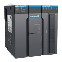
1) Terminal signal arrangement and denitions (AM600-4DA)
AO Module AM600-4DA
Terminal Arrangement No.
Terminal
Symbol
Type Function Remarks
1 V+ Output V+ of channel 0 Voltage output
2 VI- Output V-/I- of channel 0 Voltage/Current output
3 I+ Output I+ of channel 0 Current output
4 - Shielding ground
Internally connected to
housing ground
5 V+ Output V+ of channel 1 Voltage output
6 VI- Output V-/I- of channel 1 Voltage/Current output
7 I+ Output I+ of channel 1 Current output
8 - Shielding ground
Internally connected to
housing ground
9 V+ Output V+ of channel 2 Voltage output
10 VI- Output V-/I- of channel 2 Voltage/Current output
11 I+ Output I+ of channel 2 Current output
12 - Shielding ground
Internally connected to
housing ground
13 V+ Output V+ of channel 3 Voltage output
14 VI- Output V-/I- of channel 3 Voltage/Current output
15 I+ Output I+ of channel 3 Current output
16 AGND
Analog signal
ground
Analog signal ground -
17 24 V Power 24 V power supply -
18 COM Power ground Power ground -
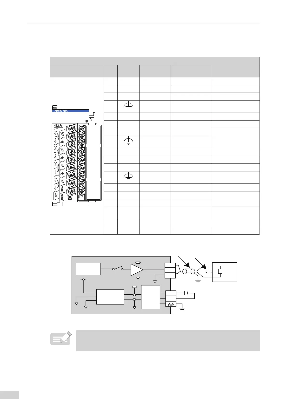
2) External wiring
%"
DPOWFSUFS
7
7
"(/%
7
%$%$
DPOWFSUFS
'JMUFS
7
7*
L
Ē
UP
.
Ē
'(
"(/%
7%$
FYUFSOBMQPXFS
7
$0.
*
.PUPSESJWF
NPEVMFBOEPUIFST
Figure 5-44 Connection for voltage-controlled signal
◆
*1 Use 2-core shielded twisted pair cable as power cable.
◆
*2 If noises or ripples are generated in external wiring
,
connect a capacitor of 0.1 to 0.47 mF 25 V
between terminals V+/I+ and VI-.
 Loading...