MD500系列
通用变频器综合手册
MD500
系列通用变频器综合手册
由于本公司持续的产品升级造成的内容变更,恕不另行通知
A00
资料编码 19010306
版权所有 深圳市汇川技术股份有限公司
Copyright Shenzhen Inovance Technology Co., Ltd.
服务与技术支持APP官方微信
深圳市汇川技术股份有限公司
Shenzhen Inovance Technology Co., Ltd.
地址:深圳市宝安区宝城70区留仙二路鸿威工业区E栋
总机:(0755)2979 9595
传真:(0755)2961 9897
客服:400-777-1260
http://www.inovance.com
苏州汇川技术有限公司
Suzhou Inovance Technology Co., Ltd.
地址:苏州市吴中区越溪友翔路16号
总机:(0512)6637 6666
传真:(0512)6285 6720
客服:400-777-1260
http://www.inovance.com
Min
Max
综合手册
二维码
销售服务联络地址
条形码位置
放置二维码后删除虚框
Warranty Agreement
The warranty period of the product is 18 months (subject to information indicated by
the barcode on the product). During the warranty period, if the product fails or is dam-
aged under the condition of normal use by following the instructions, Inovance will be
responsible for free maintenance.
Within the warranty period, maintenance will be charged for the damages due to the
following causes:
1) Improper use or uninstallation/repair/modication without prior permission
2) Fire, ood, abnormal voltage, other disasters, and secondary disasters
3) Hardware damage caused by dropping or transportation after procurement
4) Failure to operate the product by observing the User Guide provided by Inovance
5) Faults and damages caused by factors outside of the product (such as peripheral
devices)
The maintenance fee is charged according to the latest Maintenance Price List of Ino-
vance.
The Product Warranty Card is not re-issued. Keep the card and present it to the mainte-
nance personnel when seeking maintenance.
If there is any problem during the service, contact us or our agent directly.
You are assumed to agree on terms and conditions of this warranty agreement by
purchase of the product. This agreement shall be interpreted by Suzhou Inovance
Technology Co,.Ltd.
8
5
6
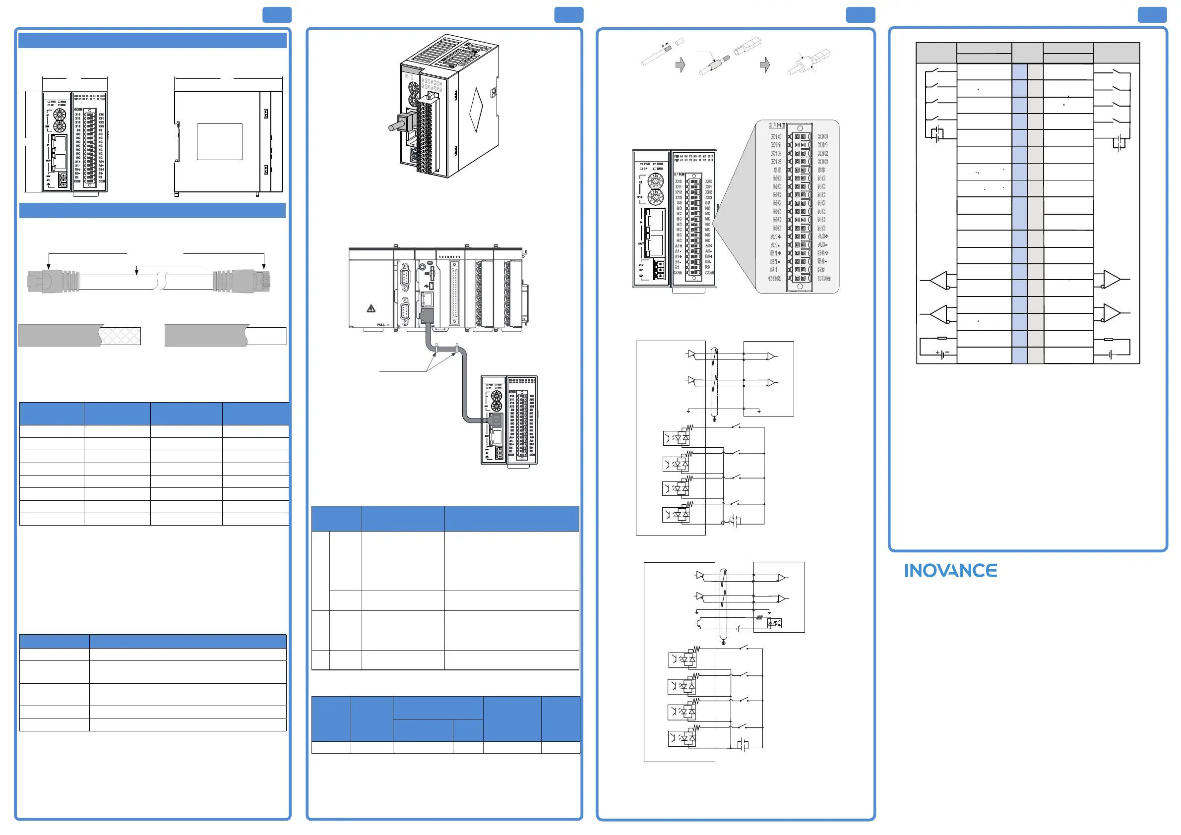
IV. Mechanical Design Reference
■ Mounting Dimensions
V. Electrical Design Reference
■ Cable Preparation
$BCMFDPOOFDUPS1$QSPOH
"8($BUFTIJFMEFEUXJTUFEQBJS
$BCMFDPOOFDUPS1$QSPOH
4IJFMEFEDBCMF 6OTIJFMEFEDBCMF
Use Cat 5e shielded twisted pair (STP) cables, with injection molded and iron
shelled connector.
■ Signal pins
Pin Signal Signal Direction
Signal
Description
1 TD+ Output Data transmission+
2 TD- Output Data transmission-
3 RD+ Input Data reception+
4 -- -- Not used
5 -- -- Not used
6 RD- Input Data reception–
7 -- -- Not used
8 -- -- Not used
■ Length requirements:
According to FastEthernet technology, when an EtherCAT bus is used, the length of
the cable between the devices must not exceed 100 meters. Exceeding this length
will attenuate the signal and aect communication.
■ Technical requirements:
100% continuity test, no short circuit, open circuit, misalignment and poor contact.
Use a shielded cable as the EtherCAT bus for network data transmission, with the
following recommended specications:
Item Specications
Cable type Flexible crossover cable, S-FTP, Cat 5e
Complied
standards:
EIA/TIA568A, EN50173, ISO/IEC11801
EIA/TI Abulletin TSB, EIA/TIA SB40-A&TSB36
Conductor cross
section
AWG26
Conductor type Twisted pair
Pair 4
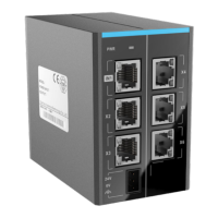
■ Communication Wiring
1) EtherCAT connection
Insert the cable into the EtherCAT port of the communication module until you
hear a click sound.
7
Figure 2 Cable connection diagram
2) Requirements for securing communication cable
To protect the communication cable from any tension and to ensure
communication stability, x the cable end which is near the device before EtherCAT
communication, as shown below:
MF K
3940
21
CN5
CN1 RS485 CN 2 CA N
CN3 EtherNET CN 4 Et herCAT
STOPRUN
CANERR
CANRUN
BF
SF
ERR
RUN
0123 7654
27654103
456 73210
I
II
PO WER
Risk of electric shock
ሿᗳ䀖⭥
'JYXJUIDBCMFUJF
3) Fault Indication and troubleshooting for EtherCAT remote communication
expansion module
EtherCAT slave station:
LED
indicator
Indication Solution
RUN
OFF
No connection between
EtherCAT master and
slave
Check conguration and parameter
assignment;
Check the communication address
Check that the length and other
specications of the network cable are
as specied.
Blinking
EtherCAT slave is in a
state other than OP
Check slave conguration for any
missing, faulty or uncongured module.
ERR Blinking
No data exchange
between EtherCAT
master and slave
Check that the cable connector is
inserted correctly;
Check that the network cable is intact;
Re-power on.
SF
Steady
ON
Output channel is faulty
For details, see the application manual
of the module.
■ Cable Selection
Material
Name
Model
Applicable Cable
Diameter
Manufacturer
Name
Crimping
Tool
Chinese
Standard/MM
AWG
Tubular lug GTVE07512 0.75. 21 Suzhou Yuanli YAC-5
■ Cable preparing procedures:
Remove the insulation of the cable so that a length of 11–14 mm of the conductor is
exposed, and put the cable through a cable marking sleeve.
Insert the exposed end into the hole of the cable lug, and then crimp it with
recommended crimping tool.
NJNN
1VUDBCMF
UISPVHITMFFWF
$SJNQ
Figure 3 Cable preparation
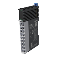
■ Terminal Layout
■ User output terminal wiring
9
4UFQQFSNPUPSESJWF
7%$
9
9
9
104
MJNJU
/&(
MJNJU
)PNF
JOQVU
&TUPQ
JOQVU
-FGUMJNJUTXJUDI
3JHIUMJNJU
TXJUDI
)PNF
TXJUDI
&TUPQ
TXJUDI
5IFMPHJDPGUIFTFTXJUDIFT
DBOCFTFUJOUIFVTFS
QSPHSBNBDDPSEJOHUPUIFJS
TQFDJ珝DDIBSBDUFSJTUJDT
FYUQPXFS
HPULSE+
HPULSE-
HSIGN+
HSIGN-
COM
GND
"
"
#
#
9KX\USUZUXJXO\K
X00
+
-
24VDC
X01
X02
X03
+
-
:XG\KRY]OZIN*
:XG\KR
Y]OZIN
*
.USK
Y]OZIN
*
+YZUVY]OZIN *
K^ZVU]KX
HP ULSE+
HP ULSE-
HS IGN+
HS IGN-
CO M
GND
A0+
A0-
B0+
B0-
S-ON
R0
CO M
24VDC
K^ZVU]KX
5IFMPHJDPGUIFTFTXJUDIFT
DBOCFTFUJOUIFVTFS
QSPHSBNBDDPSEJOHUPUIFJS
TQFDJ珝DDIBSBDUFSJTUJDT
104
MJNJU
/&(
MJNJU
)PNF
JOQVU
&TUPQ
JOQVU
Figure 4 Output terminal wiring
* The common GND of the module must be connected to the GND terminal of the
drive to reduce noise interference.
Suzhou Inovance Technology Co., Ltd.
Address: No.16 Youxiang Road, Yuexi, Wuzhong District, Suzhou 215104
Service hotline: 4000-300124
Website: http://www.inovance.com
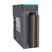
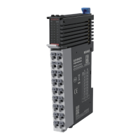
■ External Wiring
+^Z=OXOTM
:KXSOTGR
4U
Column B
9OMTGR4GSK
+^Z=OXOTM
9OMTGR4GSK
Column A
圯坒坄均
24VD C
+
-
圯坒坄均
24
VD C
+-
+
-
+
-
24 VDC
+
-
+
-
24 VDC
3536
3334
31
3
2
2930
2728
2526
23
24
2122
1718
/TV[Z
()
1718
1516
13
14
1112
910
78
5
6
34
12
/TV[Z
(
X10
)
X11
)
1920
X00
(
/TV[Z
X12
)
(
/TV[Z
X13
)
(
/TV[Z
SS
)
(
SS)53
NC
)
(
4UZIUTTKIZKJ
NC
)
(
4UZIUTTKIZKJ
NC
)
(
4UZIUTTKIZKJ
NC
)
(
4UZIUTTKIZKJ
X01
)
(
/TV[Z
X02
)
(
/TV[Z
X03
)
(
/TV[Z
SS
)(
SS)53
NC
)
(
4UZIUTTKIZKJ
NC
)
(
4UZIUTTKIZKJ
NC
)
(
4UZIUTTKIZKJ
NC
)
(
4UZIUTTKIZKJ
NC
)
(
4UZIUTTKIZKJ
NC )(
4UZIUTTKIZKJ
A1+
)(
6[RYKU[ZV[Z
A1-
)(
6[RYKU[ZV[Z
B1+
)
(
6[RYKU[ZV[Z
B1-
)
(
6[RYKU[ZV[Z
R1
)
(
+TGHRKU[ZV[Z
COM
)
(
)USSUT-4*
NC
)
(
4UZIUTTKIZKJ
NC
)
(
4UZIUTTKIZKJ
A0+
)
(
6[RYKU[ZV[Z
A0-
)
(
6[RYKU[ZV[Z
B0+
)
(
6[RYKU[ZV[Z
B0-
)
(
6[RYKU[ZV[Z
R0
)
(
+TGHRKU[ZV[Z
)USSUT-4*
4UZIUTTKIZKJ4UZIUTTKIZKJ
NC
NC
Figure 5 Module wiring diagram
*1 4-core shielded twisted pair cables are used for dierential output to reduce noise
interference;
*2 The common GND for dierential output must be connected to the GND terminal
of the servo drive to reduce noise interference.
*3 Ensure that the metal spring piece at the bottom the of the module is securely
installed. Mount the module on a well-grounded metal bracket, and ensure that the
spring piece is in good contact with the bracket.
■ Wiring Precautions
Do not bundle the cable together with AC cable, main lines, high voltage cable and
so forth, otherwise it may result in an increased noise, surge and induction.
Apply single-point grounding for the shielding of shielded cable and solder sealed
cable.
Tubed and solderless crimp terminal cannot be used with terminal block. Using
marking sleeve or insulation sleeve to cover the cable connector part of the crimp
terminals is recommended.
 Loading...