1. Overview
Thank you for purchasing the GL10-0032ETN digital output expansion module developed and manufactured
independently by Inovance.
This product provides NPN outputs, and is used together with the AM600CPU, GL10-RTU-ECT, GL10-RTU-COP,
GL10-RTU-DP and H3U modules to expand the digital output ports.
This guide describes the specications, characteristics and using methods of GL10-0032ETN digital output
expansion module. Read this guide carefully before using to ensure more safe usage. See the Medium-Sized PLC
Programming Manual to understand the use of the user program development environment and design method of
the user program of the product. You can download the latest materials from
w
w
w
.
i
n
o
v
a
n
c
e
.
c
o
m
.
2. Safety Information and Precautions
Safety information and precautions are identied into two grades: Warning and Caution. Please make sure to
operate properly with adequate safety assurance.
Indicates the improper operation which, if not avoided, may cause death or serious injury;
Indicates the improper operation which, if not avoided, may cause moderate or minor injury,
as well as equipment damage.
In some cases, even failure to follow"Cautions" may also lead to serious consequences. Please make sure to follow
both warnings and cautions, otherwise, it may cause death or serious injury, as well as product and relevant
equipment and system damage.
Please keep this guide well so that it can be read when necessary and forward this guide to the end user.
During control system design
◆ Provide a safety circuit outside the PLC so that the control system can still work safely once external power
failure or PLC fault occurs.
◆ Add a fuse or circuit breaker because the module may smoke or catch re due to long-time overcurrent
caused by operation above rated current or load short-circuit.
1
During control system design
◆ An emergency stop circuit, a protection circuit, a forward/reverse operation interlocked circuit, and a
upper position limit and lower position limit interlocked circuit must be set in the external circuits of PLC to
prevent damage to the machine.
◆ To ensure safe operation, for the output signals that may cause critical accidents, please design external
protection circuit and safety mechanism;
◆ Once PLC CPU detects abnormality in the system , all outputs may be closed; however, when a fault occurs
in the controller circuit, the output may not be under control. Therefore, it is necessary to design an
appropriate external control circuit to ensure normal operation;
◆ If the PLC's output units such as relays or transistors are damaged, the output may fail to switch between ON
and OFF states according to the commands;
◆ The PLC is designed to be used in indoor electrical environment (overvoltage category II). The power supply
must have a system-level lightning protection device, assuring that overvoltage due to lightning shock can't
be applied to the PLC's power supply input terminals, signal input terminals and output terminals and so
forth, so as to avoid damage to the equipment.
During installation
◆ Installation must be carried out by the specialists who have received the necessary electrical training and
understood enough electrical knowledge.
◆ Disconnect all external power supplies of the system before module assembly/disassembly and wiring.
Failure to do so may result in electric shock, module fault or malfunction. Failure to do so may result in
electric shock, module fault or malfunction.
◆ Do not use the PLC where there are dust, oil smoke, conductive dust, corrosive or combustible gases, or
exposed to high temperature, condensation, wind & rain, or subject to vibration and impact. Electric shock,
re and malfunction may also result in damage or deterioration to the product.
◆ The PLC is open-type equipment that must be installed in a control cabinet with lock (cabinet housing
protection level >IP20). Only the personnel who have received the necessary electrical training and
understood enough electrical knowledge can open the cabinet.
◆ Prevent metal lings and wire ends from dropping into ventilation holes of the PLC during installation.
Failure to comply may result in re, fault and malfunction.
◆ Ensure there are no foreign matters on ventilation surface. Failure to comply may result in poor ventilation,
which may cause re, fault and malfunction.
◆ Ensure the module is connected to the respective connector securely and hook the module rmly. Improper
installation may result in malfunction, fault or fall-o.
During wiring
◆ Wiring must be carried out by personnel who have received the necessary electrical training and understood
enough electrical knowledge.
◆ Disconnect all external power supplies of the system before wiring. Failure to comply may result in electric
shock, module fault or malfunction.
◆ Install the terminal cover attached to the product before power-on or operation after wiring is completed.
Failure to comply may result in electric shock.
◆ Perform good insulation on terminals so that insulation distance between cables will not reduce after cables
are connected to terminals. Failure to comply may result in electric shock or damage to the equipment.
◆ Prevent dropping metal lings and wire ends drop into ventilation holes of the PLC at wiring. Failure to
comply may result in re, fault and malfunction.
◆ The external wiring specication and installation method must comply with local regulations. For details,
see the wiring section in this guide.
◆ To ensure safety of equipment and operator, use cables with sucient diameter and connect the cables to
ground reliably.
◆ Wire the module correctly after making clear of the connector type. Failure to comply may result in module
and external equipment fault.
◆ Tighten bolts on the terminal block in the specied torque range. If the terminal is not tight, short-circuit,
re or malfunction may be caused. If the terminal is too tight, fall-o, short-circuit, re or malfunction may
be caused.
◆ If the connector is used to connect with external equipment, perform correct crimping or welding with the
tool specied by manufacturer. If connection is in poor contact, short-circuit, re or malfunction may be
caused.
◆ A label on the top of the module is to prevent foreign matters entering the module. Do not remove the label
during wiring. Remember to remove it before system operation, facilitating ventilation.
◆ Do not bundle control wires, communication wires and power cables together. They must be run with
distance of more than 100 mm. Otherwise, noise may result in malfunction.
◆ In application scenarios with serious interference, shielded cables should be used as the input or output
cables of high-frequency signals to ensure the resistance to interference.
During maintenance & inspection
◆ Maintenance & inspection must be carried out by personnel who have the necessary electrical training and
experience.
◆ Do not touch the terminals while the power is on. Failure to comply may result in electric shock or
malfunction.
◆ Disconnect all external power supplies of the system before cleaning the module or re-tightening screws on
the terminal block or screws of the connector. Failure to comply may result in electric shock.
◆ Disconnect all external power supplies of the system before removing the module or connecting/removing
the communication wirings. Failure to comply may result in electric shock or malfunction.
◆ Get acquainted with the guide and ensure safety before online modication, forcible output, and RUN/STOP
operation.
◆ Disconnect the power supply before installing/removing the extension card.
At disposal
◆ Treat scrapped module as industrial waste. Dispose the battery according to local laws and regulations.
3. Product Information
■ Model and Nameplate
.BSL %FTDSJQUJPO
-
-PDBMNPEVMF
.BSL 4FSJFT
TFSJFT
.BSL %FTDSJQUJPO
(
.BSL *01PJOU
PVUQVUQPJOUT
.BSL 0VUQVU5ZQF
5SBOTJTUPSTJOL5/
(FOFSBM.PEVMF
.BSL *01PJOU
JOQVUQPJOU
.BSL .PEVMF5ZQF
-PHJD*0FYQBOTJPO&
.PEFM
*OQVU
0VUQVU
4FSJBM/P
/BNFQMBUF
.0%&-盘(-&5/
108&3*/165盘/0/&
065165盘/0/&
9999999999999999
7FSTJPO/P
7&399999
9999999999999999
Figure 1 Description of model and nameplate
Model Classication Description Applicable to
GL10-0032ETN Digital output module
32-point DO module;
transistor output (Drain)
AM600 series, H3U
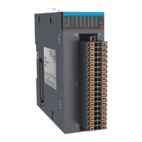
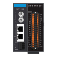
■ External Port
Figure 2 Diagram of digital output module interface
2 3
User Guide
GL10
-0032ETN
Digital Output Module
*19011105A01*
19011105A01