1
2
3 4
I. Overview
Thank you for purchasing the GR10-2PHE high speed dierential pulse positioning
module developed and manufactured independently by Inovance. This product
delivers 2*4 MHz high-speed dierential outputs. It supports multiple pulse output
modes, including direction+pulse or CW + CCW. It also supports homing positioning
and left and right limiting. It is ideal choice for applications require a large number
of axes.
This guide describes the specications, characteristics and using methods of the
product. Please read this guide carefully before using to ensure safe usage. Visit our
website (www.inovance.com) for the latest version of the guide.
II. Safety Instructions
Safety Precautions
1. Before installing, using, and maintaining this equipment, read the safety
information and precautions thoroughly, and comply with them during operations.
2. To ensure the safety of humans and equipment, follow the signs on the
equipment and all the safety instructions in this user guide.
3. The "CAUTION", "WARNING" and "DANGER" signs are only supplements to the
safety instructions.
4. Use this equipment according to the designated environment requirements.
Damage caused by improper usage is not covered by warranty.
5. Inovance shall take no responsibility for any personal injuries or property damage
caused by improper usage.
Safety Levels and Denitions
: Indicates that failure to comply with the notice may result in severe
personal injuries or even death.
: The "CAUTION" sign indicates that failure to comply with the notice may
result in minor or moderate personal injury or damage to the equipment.
Please keep this guide well so that it can be read when necessary and forward this
guide to the end user.
During control system design
◆ Provide a safety circuit outside the PLC so that the control system can still work safely
once external power failure or PLC fault occurs.
◆ Add a fuse or circuit breaker because the module may smoke or catch re due to long-
time overcurrent caused by operation above rated current or load short-circuit.
◆ An emergency stop circuit, a protection circuit, a forward/reverse operation inter-
locked circuit, and a upper position limit and lower position limit interlocked circuit
must be set in the external circuits of PLC to prevent damage to the machine.
◆ To ensure safe operation, for the output signals that may cause critical accidents,
please design external protection circuit and safety mechanism;
◆ Once PLC CPU detects abnormality in the system , all outputs may be closed; howev-
er, when a fault occurs in the controller circuit, the output may not be under control.
Therefore, it is necessary to design an appropriate external control circuit to ensure
normal operation;
◆ If the PLC output units such as relays or transistors are damaged, the output may fail
to switch between ON and OFF states according to the commands;
◆ The PLC is designed to be used in indoor electrical environment (overvoltage category
II). The power supply must have a system-level lightning protection device, assuring
that overvoltage due to lightning shock cannot be applied to the PLC power supply in-
put terminals, signal input terminals and output terminals and so forth, so as to avoid
damage to the equipment.
Installation
◆ Installation must be carried out by the specialists who have received the necessary
electrical training and understood enough electrical knowledge.
◆ Disconnect all external power supplies of the system before removing/installing the
module. Failure to do so may result in electric shock, module fault or malfunction.
◆ Do not use the PLC where there are dust, oil smoke, conductive dust, corrosive or
combustible gases, or exposed to high temperature, condensation, wind & rain, or
subject to vibration and impact. Electric shock, re and malfunction may also result
in damage or deterioration to the product.
◆ The PLC is open-type equipment that must be installed in a control cabinet with
lock (cabinet housing protection >IP20). Only the personnel who have received the
necessary electrical training and understood enough electrical knowledge can open
the cabinet.
◆ Prevent metal lings and wire ends from dropping into ventilation holes of the PLC
during installation. Failure to comply may result in re, fault and malfunction.
◆ Ensure there are no foreign matters on ventilation surface. Failure to comply may
result in poor ventilation, which may cause re, fault and malfunction.
◆ Ensure the module is connected to the respective connector securely and hook the
module rmly. Improper installation may result in malfunction, fault or fall-o.
Wiring
◆ Wiring must be carried out by personnel who have received the necessary electrical
training and understood enough electrical knowledge.
◆ Disconnect all external power supplies of the system before wiring. Failure to comply
may result in electric shock, module fault or malfunction.
◆ Install the terminal cover attached to the product before power-on or operation after
wiring is completed. Failure to comply may result in electric shock
◆ Perform good insulation on terminals so that insulation distance between cables will
not reduce after cables are connected to terminals. Failure to comply may result in
electric shock or damage to the equipment.
◆ Prevent dropping metal lings and wire ends drop into ventilation holes of the PLC at
wiring. Failure to comply may result in re, fault and malfunction.
◆ The external wiring specication and installation method must comply with local
regulations. For details, see the wiring section in this guide.
◆ To ensure safety of equipment and operator, use cables with sucient diameter and
connect the cables to ground reliably.
◆ Ensure that all cables are connected to the correct interface. Failure to comply may
result in module and external equipment fault.
◆ Tighten bolts on the terminal block in the specied torque range. If the terminal is not
tight, short-circuit, re or malfunction may be caused. If the terminal is too tight, fall-
o, short-circuit, re or malfunction may be caused.
◆ If the connector is used to connect with external equipment, perform correct crimping
or welding with the tool specied by manufacturer. If connection is in poor contact,
short-circuit, re or malfunction may be caused.
◆ A label on the top of the module is to prevent foreign matters entering the module. Do
not remove the label during wiring. Remember to remove it before system operation,
facilitating ventilation.
◆ Do not bundle control wires, communication wires and power cables together. They
must be run with distance of more than 100 mm. Otherwise, noise may result in mal-
function.
◆ Select shielded cable for high-frequency signal input/output in applications with
serious interference so as to enhance system anti-interference ability.
Operation and Maintenance
◆ Maintenance & inspection must be carried out by personnel who have the necessary
electrical training and experience.
◆ Do not touch the terminals while the power is on. Failure to comply may result in elec-
tric shock or malfunction.
◆ Disconnect all external power supplies of the system before cleaning the module or
re-tightening screws on the terminal block or screws of the connector. Failure to com-
ply may result in electric shock.
◆ Disconnect all external power supplies of the system before removing the module or
connecting/removing the communication wirings. Failure to comply may result in
electric shock or malfunction.
◆ Get with the guide and ensure safety before online modication, forcible output, and
RUN/STOP operation.
◆ Disconnect the power supply before installing/removing the extension card.
Disposal
◆ Treat scrapped module as industrial waste. Dispose the battery according to local laws
and regulations.
III. Product Information
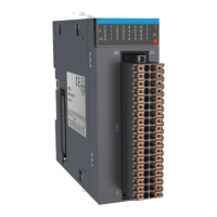
■ Model Number and Nameplate
(31)&
.BSL 4FSJFT
.BSL %FTDSJQUJPO
(
.BSL 0VUQVUT
.BSL .PEVMF5ZQF
.OMNYVKKJ*/,,U[ZV[Z
V[RYKVUYOZOUTOTM
1)
(FOFSBM.PEVMF
.BSL "VY'VODUJPO
&UIFS$"5DPNNVOJDBUJPO&
3
3FNPUFNPEVMF
3UJKR
8GZKJOTV[Z
8GZKJU[ZV[Z
9KXOGR4U
4GSKVRGZK
MODEL GR10-2PHE
POWER INPUT24VDC 250mA
OUTPUT5VDC 150mA DIFF LOAD
XXXXXXXXXXXXXXXX
<KXYOUT4U
VER:XXXXX
XXXXXXXXXXXXXXXX
Figure 1 Description of model and nameplate
Model Category Description
Applicable
Model
GR10-2PHE
EtherCAT high-speed
dierential pulse
positioning module
Supports 2-channel high-
speed dierential output
pulse and 8 inputs
AM600 series
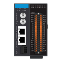
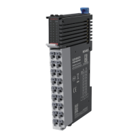
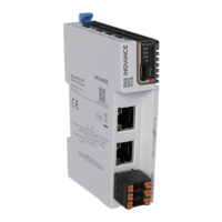
■ External Interface
No. Interface Name Function
① State indicator
PWR Power indicator Green
ON when power
supply is switched on
RUN
Running status
indicator
Green
ON when the
module is in normal
operation
SF Fault indicator Red
ON when the module
is faulty
ERR
State machine
error indicator
Red
ON when an error
occurs in the state
machine
② Signal indicator
CH0/1 Indicator Green
On when channel 0/1
is ready to output
A/B
Pulse+direction
Indicator
Green /
X0-X3
Digital input
indicator
Green
On when the input
signal is active
③
Address DIP
switch
16-bit station address rotary switch. Decimal slave
address = ADDR1*16+ADDR0 (address 0–255)
④
EtherCAT
communication
port
X1 IN: EtherCAT input
X2 OUT: EtherCAT output for connecting back-end
EtherCAT slaves
⑤
24 V power input
terminal
For module power supply input
⑥
User output
terminals
See "Electrical Design Reference" for details
19011286
A01
■ General Specications
Item Specications
Power supply
specications
24 VDC (20.4 VDC to 28.8 VDC) (–15% to +20%)
Input current Max. 0.25 A
Number of
positioning
channels
2
Ordinary output
signal
Sink output: 24 V, response time: 0.5 ms
Dierential pulse
output
Pulse+direction, CW/CCW, A/B (output frequency: 4 MHz)
Digital input 8 (sink and source)
System program
upgrade method
USB rmware upgrade
Positioning
Absolute pulse positioning, relative pulse positioning, speed
control, multiple homing methods
Communication
protocol
EtherCAT industrial real-time bus protocol, 100 Mbps
Network port/
network cable
Standard network port with Cat 5e network cables below 100
meters
Station number
range
1–255 if set by DIP switch
0–65535 if automatically allocated through a network bus.
Operating
temperature
-5–55℃
Storage
temperature
-25–70℃
Humidity 10–95%, no-condensation
IP rating IP20
The specic performance indicators are as follows:
Item Specications
Communication protocol EtherCAT protocol
Service supported CoE (PDO, SDO)
Min. sync period 500 us (TYP)
Synchronization mode
Input and output synchronization or DC-distributed
clock
Physical layer 100BASE-TX
Baud rate 100 Mbit/s (100Base-TX)
Duplex mode Full duplex
Topological structure Linear topological structure
Transmission medium Network cables, see "Electrical Design Reference"
Transmission distance Less than 100 m between two nodes
EtherCAT frame length 44–1,498 bytes
Process data Max. 1486 bytes per frame
Synchronization jitter of
two slave stations
< 1us
Update time Approx. 500 us
■ Output specication
Item SINK output Item Dierential output
Output type Transistor NPN Output type 5 V dierential output
ON response
time
Less than 0.5 ms Insulation Optocoupler isolation
Insulation Optocoupler isolation
Max. output
frequency
4 MHz
Open-circuit
leakage
current
Less than 0.1 mA/30 VDC
Output
mode
Pulse+direction, A/B
phase single frequency,
CW/CCW
Min. load 5 mA (DC5V–24V)
Number of
channels
2
Max. load
Resistive load: 0.5 A/point
Inductive load: 7.2 W/24 V
Lamp load: 0.9 W/24 V
-- --
■ Input specication
Item Specications
Input type SINK/SOURCE input
Input voltage DC 24 V
Input resistance 3.3KΩ
Input is ON Input current is above 3.5 mA
Input is OFF Input current is below 1.5 mA
GR10
-2PHE HS Dierential
Pulse Positioning Module
User Guide
MD500系列
通用变频器综合手册
MD500
系列通用变频器综合手册
由于本公司持续的产品升级造成的内容变更,恕不另行通知
A00
资料编码 19010306
版权所有 深圳市汇川技术股份有限公司
Copyright Shenzhen Inovance Technology Co., Ltd.
服务与技术支持APP官方微信
深圳市汇川技术股份有限公司
Shenzhen Inovance Technology Co., Ltd.
地址:深圳市宝安区宝城70区留仙二路鸿威工业区E栋
总机:(0755)2979 9595
传真:(0755)2961 9897
客服:400-777-1260
http://www.inovance.com
苏州汇川技术有限公司
Suzhou Inovance Technology Co., Ltd.
地址:苏州市吴中区越溪友翔路16号
总机:(0512)6637 6666
传真:(0512)6285 6720
客服:400-777-1260
http://www.inovance.com
Min
Max
综合手册
二维码
销售服务联络地址
条形码位置
放置二维码后删除虚框
*19011286A01*