Inovance MDBUN Series Braking Unit User Manual
Page 13 of 24
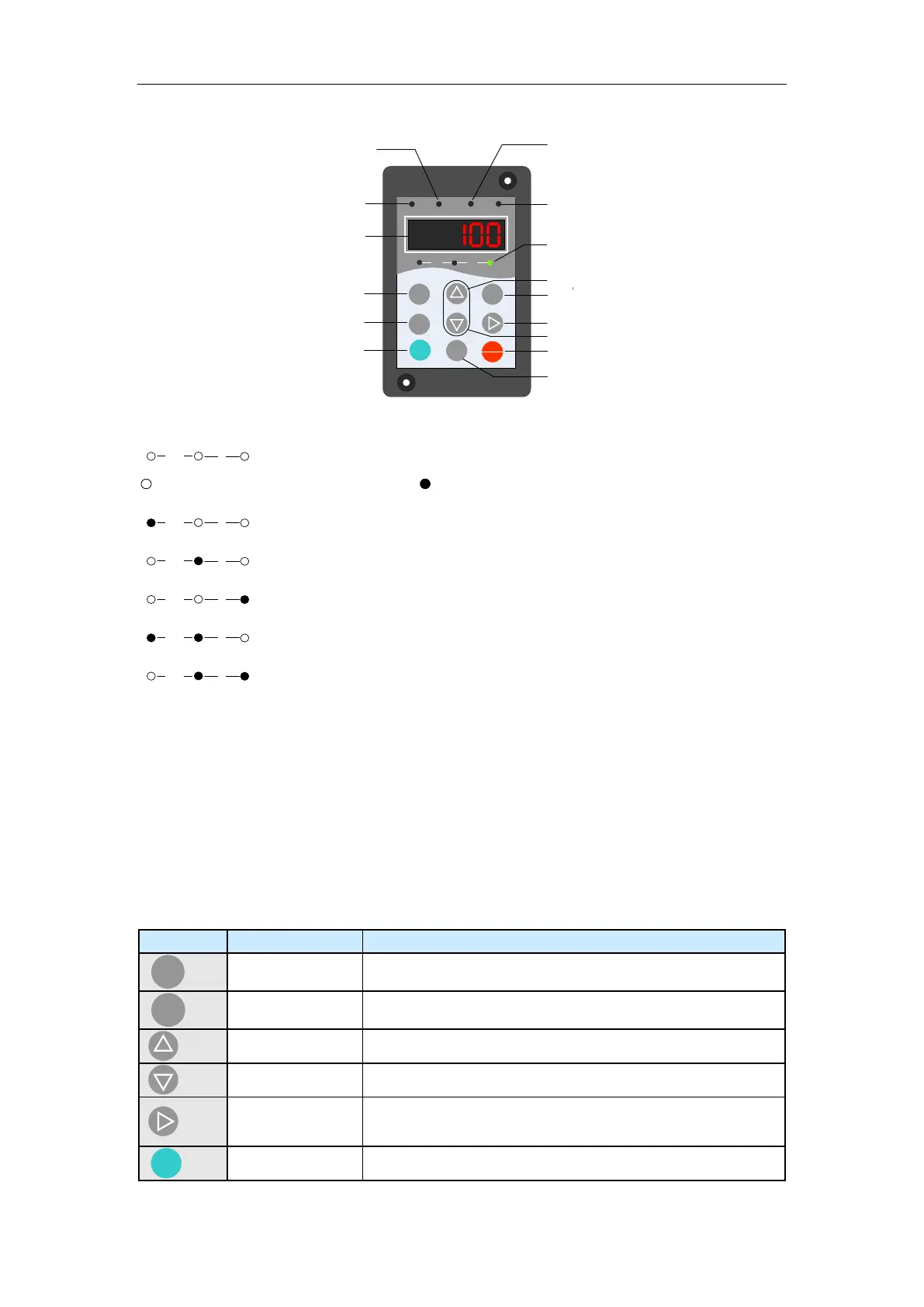
Figure 4-3 Diagram of the operation panel
MF.K
RUN
STOP
RES
QUICK
PRG ENTER
RUN
LOCAL/REMOT FED/REV TUNE/TC
RPM
%
A VHz
Master/Slave
indicator
Reserved
Running
indicator
Digital display
Programming
key
Reserved
Reserved
Reserved
Reset key
Shift key
Increment key
Decrement key
Confirm key
Unit indicator
Fault indicator
Unit Indicators
: Unit indicators, used for displaying the current data unit.
means that the indicator is off, and means that the indicator is on.
Hz: unit of frequency
A: unit of current
V: unit of voltage
RPM: unit of rotation speed
%: percentage
Running Indicator
This indicator is on when the braking unit is in running state.
Master/Slave indicator
ON indicates that the braking unit is in slave mode, and OFF indicates that the braking unit
is in ON state.
Digital Display
The 5-digit LED display is able to display the bus voltage, maximum continuous braking
current, IGB module base plate temperature, present braking rate, and fault code.
Keys on the Operation Panel
Enter or exit Level I menu.
Enter the menu interfaces level by level, and confirm the
parameter setting.
Increase data or function code.
Decrease data or function code.
Select the displayed parameters in turn in the stop or running
state, and select the digit to be modified when modifying
parameters.
 Loading...