Intel Desktop Board DH61HO Technical Product Specification
44
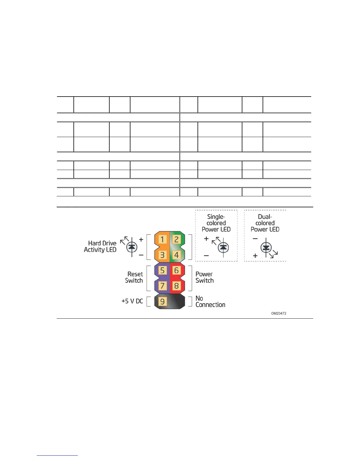
2.2.2.4 Front Panel Header
This section describes the functions of the front panel header. Table 20 lists the signal
names of the front panel header. Figure 10 is a connection diagram for the front panel
header.
Table 20. Front Panel Header
Pin
Signal
In/
Out
Description
Pin
Signal
In/
Out
Description
Hard Drive Activity LED Power LED
1 HD_PWR Out Hard disk LED
pull-up to +5 V
2 FP_LED+ Out Front panel green
LED
3 HDA# Out Hard disk active
LED
4 FP_LED− Out Front panel yellow
LED
Reset Switch On/Off Switch
5 Ground Ground 6 PWR# In Power switch
7 FP_RESET# In Reset switch 8 Ground Ground
Power Not Connected
9 +5 V Power 10 N/C Not connected
Figure 10. Connection Diagram for Front Panel Header
 Loading...