48
2.2.2.4 Front Panel Header
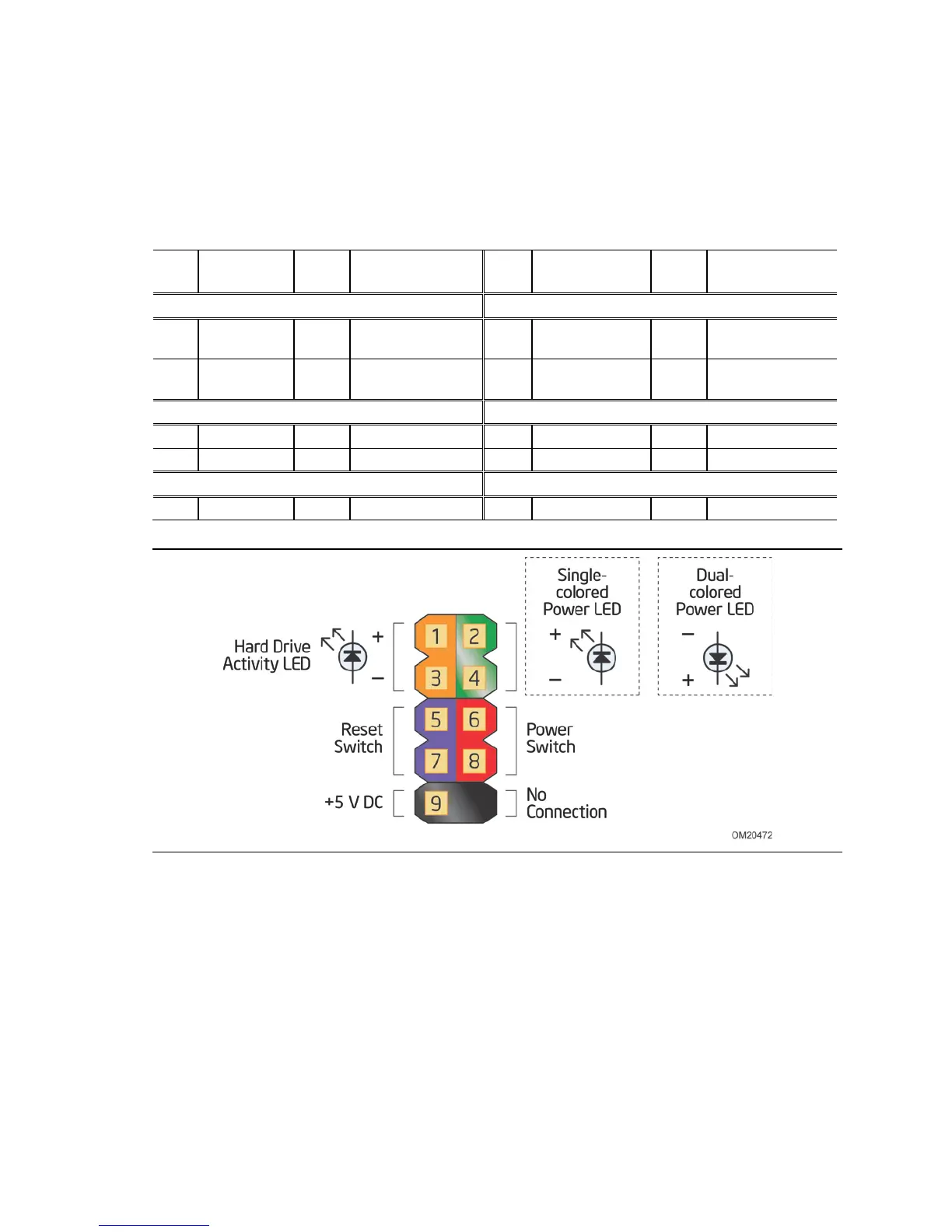
This section describes the functions of the front panel header. Table 24 lists the signal
names of the front panel header. Figure 11 is a connection diagram for the front panel
header.
Table 24. Front Panel Header
Pin
Signal
In/
Out
Description
Pin
Signal
In/
Out
Description
Hard Drive Activity LED Power LED
1 HD_PWR Out Hard disk LED
pull-up to +5 V
2 FP_LED+ Out Front panel green
LED
3 HDA# Out Hard disk active
LED
4 FP_LED− Out Front panel yellow
LED
Reset Switch On/Off Switch
5 Ground Ground 6 PWR# In Power switch
7 FP_RESET# In Reset switch 8 Ground Ground
Power Not Connected
9 +5 V Power 10 N/C Not connected
Figure 11. Connection Diagram for Front Panel Header
2.2.2.4.1 Hard Drive Activity LED Header
Pins 1 and 3 can be connected to an LED to provide a visual indicator that data is
being read from or written to an internal storage device. Proper LED function requires
a SATA hard drive or optical drive connected to an onboard SATA connector.
 Loading...