Technical Reference
49
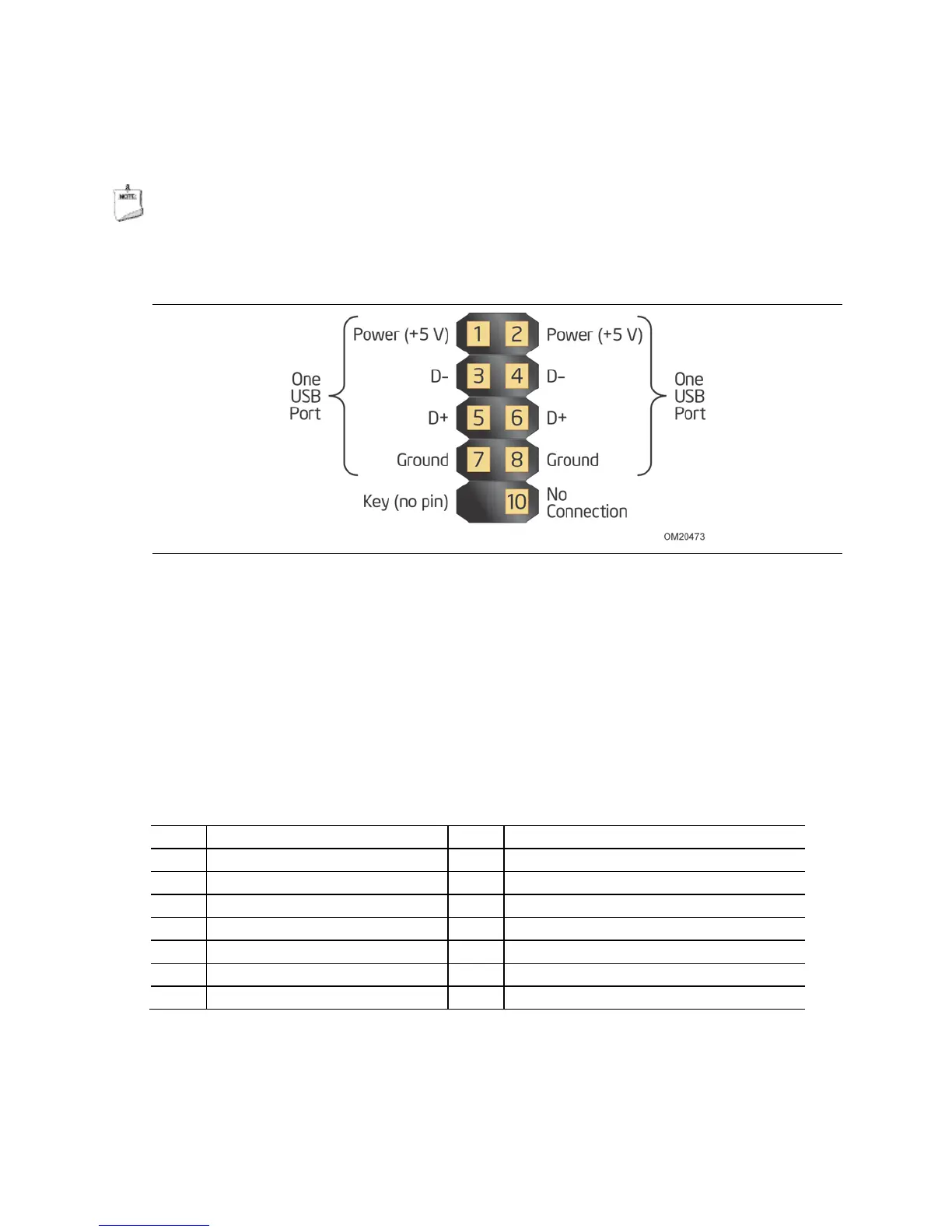
2.2.2.6 Front Panel USB 2.0 Headers
Figure 12 is a connection diagram for the front panel USB 2.0 headers.
NOTE
• The +5 V DC power on the USB headers is fused.
• Use only a front panel USB connector that conforms to the USB 2.0 specification for
high-speed USB devices.
Figure 12. Connection Diagram for Front Panel USB 2.0 Headers
2.2.2.7 Low Pin Count (LPC) Debug Header
During the POST, the BIOS generates diagnostic progress codes (POST codes) to I/O
port 80h. If the POST fails, execution stops and the last POST code generated is left at
port 80h. This code is useful for determining the point where an error occurred.
Displaying the POST codes requires a POST card that can interface with the Low Pin
Count (LPC) Debug header. The POST card can decode the port and display the
contents on a medium such as a seven-segment display.
Table 27. LPC Debug Header
Pin Signal Name Pin Signal Name
1 CK_33M_DEBUG 2 GND
3 PLTRST# 4 LFRAME#
5 LAD0 6 LAD1
7 LAD2 8 LAD3
9 GND 10 GND
11 +3.3 V 12 +3.3 V
13 Not Connected 14 +3.3 V
 Loading...