9
z
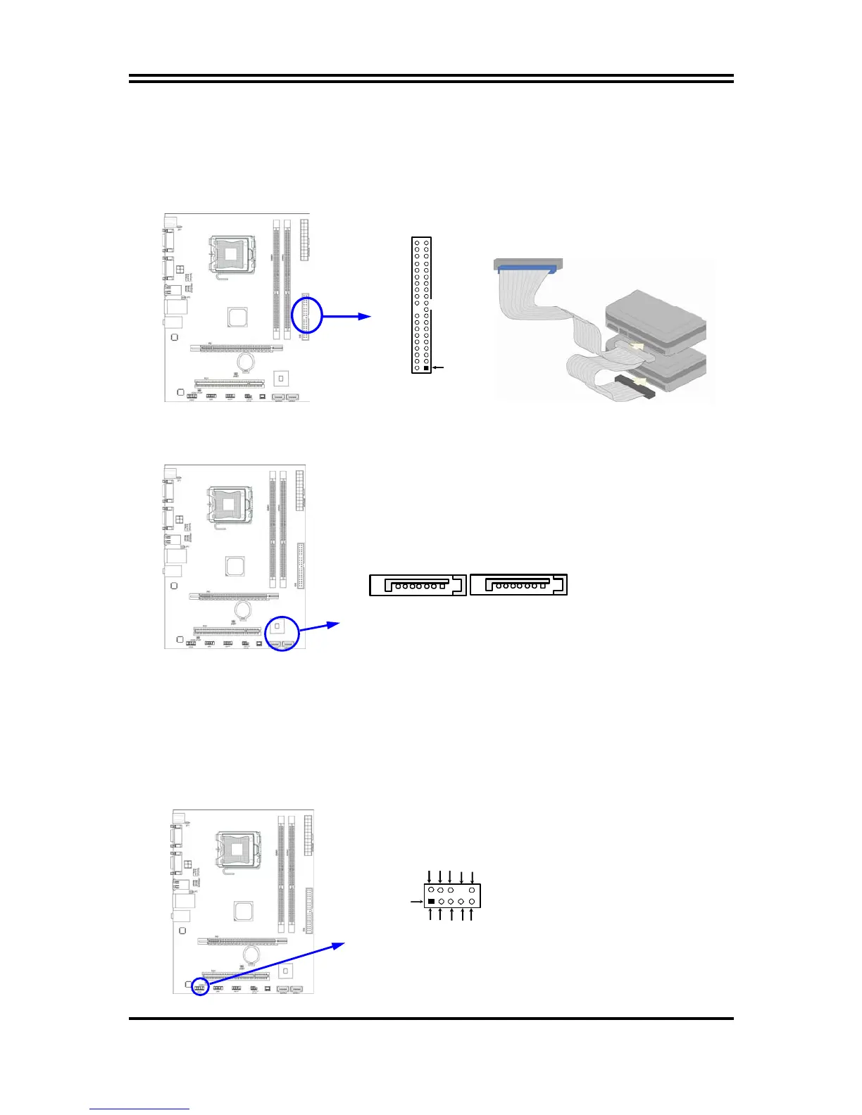
Two hard disks can be connected to each connector. The first HDD is
referred to as the “Master” and the second HDD is referred to as the “Slave”.
z
For performance issues, we strongly suggest you don’t install a CD-ROM or
DVD-ROM drive on the same IDE channel as a hard disk. Otherwise, the
system performance on this channel may drop.
IDE Connector
Pin 1
IDE1
(9) Serial-ATA Port connector: SATA1 / SATA2
These connectors support the provided Serial ATA and Serial ATA2 IDE hard disk
cable to connecting the motherboard and serial ATA hard disk.
Serial-ATA1 & 2 Compatible Connectors
SATA2
(10)
Serial COM Port: COM1
COM1 is the 9-pin connector. The On-board serial port can be disabled through
BIOS SETUP.
(11) VGA Connector (15-pin D-Sub) Connector: VGA
VGA is the 15-pin D-Subminiature female connector for display monitor.
3-2 Headers
(1) Line-Out/MIC Header for Front Panel (9-pin): AUDIO1
This header is connected to Front Panel Line-out, MIC connector with cable.
Line-Out, MIC Headers
AUDIO
Pin 1
Lineout2-L
Lineout2-R
Sense-FB
Audio-GND
LINE2-JD
Audio-JD
2
9
10
KEY
MIC2-L
MIC2-JD
MIC2-R
 Loading...