P/N 466-5305 • Rev A • 24JAN17 1 / 4
TX-E721 Fresnel Lens Pet Immune PIR
Description
This is the Installation Sheet for the TX-E721 Fresnel Lens Pet Immune PIR
A motion sensor (passive-infrared or PIR) detects movement within a
specific area by sensing the infrared energy emitted from a body as it
moves across the sensor’s field of view. When this motion is detected, the
sensor transmits an alarm signal to the control panel.
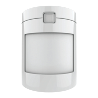
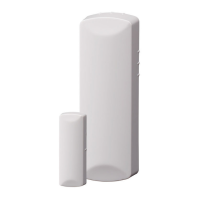
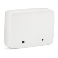
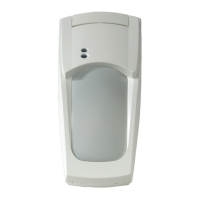
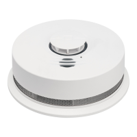
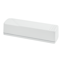
Figure 1: Pet Immune SAW PIR Motion Sensors
Use these motion sensors to protect locations where door/window sensors
are impractical or not needed. For example, use a motion sensor to protect
large areas or open floor plans. Motion sensors also provide backup
protection for door/window sensors.
The Pet Immune TX-E721 utilizes advanced signal processing, a new
custom designed lens, and a new custom designed sensing element. The
combination of these improvements provides false alarm immunity for pets
with a combined weight of up to 40 pounds while still providing superior
human catch performance.
These wireless motion sensors include the following features:
• 35 by 40 ft. (10.6 m by 12 m) coverage area.
• Three minute transmitter lockout time after an alarm that helps extend
battery life.
• Cover-activated tamper
• Supervisory signals transmitted every 64 minutes to the control panel.
• Sensor low battery reports (trouble) to the control panel.
• Field-selectable sensitivity options.
Installation
Installation Guidelines
• Temporarily place the sensor in its intended mounting location.
Program and final test the sensor before permanently mounting it.
• If possible, locate sensors within 100 ft. (30.5 m) of the panel. While a
transmitter may have a range of 500 ft. (152 m) or more out in the
open, the environment at the installation site can have a significant
effect on transmitter range. Sometimes a change in sensor location
can help overcome adverse wireless conditions.
• The recommended mounting height is 7 1/2 ft.
• Position the sensor to protect an area where an intruder would be most
likely to walk across the detection pattern See Figure 2.
Figure 2: Overhead Detection Path
• Mount the motion sensor on a rigid surface which is free from
vibrations.
• Do not mount the sensor near duct work or other large metallic
surfaces which may affect the RF signals (see RF Testing). Actual
acceptable transmitter range should be verified for each installation.
• Mount the sensor permanently on a flat wall or in a corner. Do not set it
on a shelf.
• Windows should be closed in any area which has an armed motion
sensor.
• The sensor must be incline-mounted at a mounting height of 7.5 ft. See
Figure 3.
Figure 3: Wall Mount Options
• Room temperature must be kept between 60° and 120°F (16° and 49°
C).
• Position the sensor so it faces a solid reference point, like a wall.
Programming
Refer to the panel documentation for information on programming the
sensor into the panel.
To Trip the Sensor
1. Set the panel to program mode.
2. Proceed to the Learn Sensors menu.