• Disconnectpoweratthecircuitbreaker(s)
ordisconnectswitch(es)beforebeginning
installationandbeforeservicing.
• Morethanonecircuitbreakeror
disconnectswitchmayberequiredto
de-energizetheequipmentbefore
servicing.
• Donotusethemanualoffpositionofthe
timerforequipmentservice.Always
disconnectthepoweratthecircuit
breaker(s)ordisconnectswitch(es).
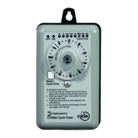
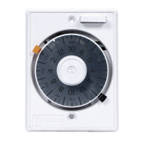
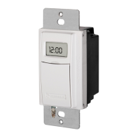
TheCT2000Timerprovidesrepetitivecycling
forfans,misters,foggers,feeders,process
equipmentandothershortcycleapplications.
Thetimerisfieldadjustableforapercentage
oftotalcycleduration.CycleTimes
(durations)canbesetfrom30secondstoa
maximumof4hrs.withONdurationsfrom1
secondupto232minutes.Thepercentageof
totalONtimeisselectedusingtherotary
knob,whichprovides30separatedetent
positionsforpreciseselection.Indicatorsare
providedforeachCycleTime.CycleTimes
are:30seconds,1,3,5,10,or30minutes,1
or4hours.
Powerinputtothetimermaybeanystandard
120or240volt60HzACsupply.Aninternal
switchallowsquickandeasyconfiguration.
NOTE:Timerisshippedin240Vposition.
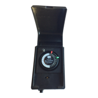
Thetimerenclosureincludestwomounting
holeson5-3/16”centersandaknockoutfor
1/2”conduitconnection.
Safety Precautions
•Theconnectionandinstallationof
electricaldevicesmayonlybecarried
outbyaqualifiedelectrician.
•Interventionsinandchangestothe
devicewillvoidthewarranty.
•Observeyournationalregulationsand
therespectivesafetyprovisions.
INSTALLATION
1.Determinedesiredmountinglocation.
2.Loosencoverscrew,liftoffcoverand
disconnectthecircuitboardcable.
3.Mounttimersecurelyusing1or2screws
ofappropriatelength,with#8mindia.
(screwsnotsupplied)Useadrilltoopenthe
lowerholeinbaseifnecessary.Thelower
holemustbesecuredwithascrewafter
opening.Tightenscrewsasrequired,butdo
notovertighten.
4.Connectconduithubstoconduitbefore
connectingthehubstothebracket.After
insertinghubsintobracket,carefullytighten
hublocknut.Donotover-torque.
5.WireinaccordancewithNationalandLocal
Codes.Makesurethewiringconnectionsfor
ClockPowerareasshownfor120or240
voltsACinput.PositionSW1intheproper
positionfor120Vor240VClockPower
operation.(Timerisshippedin240Vposition.)
6.Makeloadconnectionsasshown.Note
thattheredwiresareconnectedtoisolated
relaycontactstoallowtheloadtobe
poweredfromadifferentcircuit/voltagethan
the“ClockPower”.Youmustsupplypower
tooneoftheRedwiresandconnecttheother
Redwiretoyourload.
7.Grounding:Terminateallgroundwiresto
thegroundlug/screwonthebracket.
8.Reversestep2toreplacecover.Besureto
reconnectthecircuitboardconnector.Secure
coverwithcoverscrew;donotovertighten.
9.Restorepowertotimeratdisconnector
breakerpanel.
CYCLE TIME SETUP
ToProgramCycleTimer:
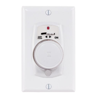
1.Turnknobuntilthe“SelectCycleTime”
arrowalignswithtriangletochoosetotal
cycletime.
2.PushtheSelectCycleTimebuttontoscroll
throughcycletimes.
3.Pushandholdbuttontosavedesiredtime
(LEDBlinks).
4.Turnknobuntildesiredpercentageof
cycletimealignswithtriangle.
Turningknobtoany%positionwillinitiatea
newONperiodfortheselectedCycleTime.
Higherpercentagepositionsprovide
additionalONtime,andlessOFFtime,as
shownbelow.
ApermanentONandapermanentOFF
positionareprovidedtoallowmanual
overrideofthecycleatanytime.
DonotusethemanualOFFpositionfor
equipmentservice.Alwaysdisconnectpower
atthedisconnectswitch(es)orbreakerpanel.
TheOFFindicatorwillbesteadyREDinthe
OFFpositionandduringtheOFFportionof
thecycles.
TheONindicatorwillbesteadyGREENinthe
ONpositionandduringtheONportionofthe
cycles.
TheyellowCycleTimeindicatorwillbeON
exceptwheninthepermanentONorOFF
positions.
CT2000 SERIES
CYCLE PERCENTAGE TIMER
Cycle Time Selector ON Time OFF Time
Duration Knob %
30sec. 10% 3sec. 27sec.
30sec. 50% 15sec. 15sec.
30sec. 80% 24sec. 6sec.
10min. 10% 1min. 9min.
10min. 50% 5min. 5min.
10min. 80% 8min. 2min.
1hour 10% 6min. 54min.
1hour 50% 30min. 30min.
1hour 80% 48min. 12min.
4hours 10% 24min.216min.
4hours 50%120min.120min.
4hours 80%192min.48min.
Risk of Electric Shock
Risk of Electric Shock
SPECIFICATIONS
InputVoltage:120VACor240VAC,60Hz
Thistimerhasanenvironmentaloperating
temperaturerangeof-10˚C(14˚F)to+60˚C
(140˚F).
Theinputisprotectedforupto6000volt
3000amppowersurges.
Overalldimensions:31/2inchesx65/8
inchesx31/4inches.
Voltage Load N.O.Contact
240VAC GeneralPurpose 20A
120VAC Motor 1HP
240VAC Motor 2HP
240VAC Tungsten 5A
240VAC PilotDuty 470VA
277VAC Ballast 10A
28VDC Resistive 20A
CLOCK
POWER
120/240
VAC
BLK
WHT
RED
RED
LOAD
LOAD
POWER
LINE
N/LINE
Upper
MountingHole
Lower
Mounting
Hole
SW1
120Vor240V
Circuit
Board
Connector
Ground
Screw
Location