Electronic 24-Hour
Time Switch
Time Switch
Input Voltage: 120/208/240/277 VAC, 50/60 Hz•
Power Consumption: 6.0 watts max.•
ContactConguration:SPST(ET1105C),DPST(ET1125C),and•
SPDT(ET1115C).Seewiringdiagramsonnextpage.
Switch Ratings—ET1105C, ET1125C (per pole)
30AInductive/Resistive:24/120/208/240/277VAC,60Hz•
20A Ballast: 120-277 VAC, 60 Hz•
20AResistive:28VDC•
5ATungsten:120/240VAC,60Hz•
1 HP: 120 VAC, 60 Hz•
2 HP: 240 VAC, 60 Hz•
Switch Ratings—ET1115C (NO/NC) Normally Open/Normally Closed Contact
20A/10AInductive/Resistive:120/208/240/277VAC,60Hz•
20A/10AResistive:28VDC•
6A/3A Ballast: 120-277 VAC, 60 Hz•
5A/3A:120/240VACTungsten•
1 HP / ¼ HP: 120 VAC, 60 Hz•
2 HP / ½ HP: 240 VAC, 60 Hz•
Set Points (Events)—EachloadoutputoftheTimeSwitchcansupport
upto14timedONand14timedOFFeventsperday.
Battery-Powered Clock Operation—2yearsminimum(uses2AAA
industrialgradealkalinebatteries,supplied)
Minimum ON or OFF time—1 minute
Maximum ON or OFF time—23hours,59minutes
Shipping Weight—2.5lb.(1.1kg)
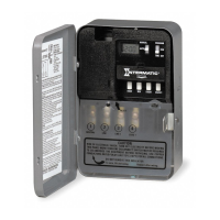
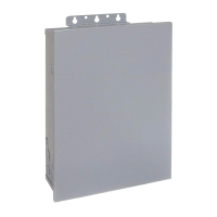
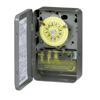
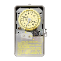
Enclosures—Threeenclosureoptionsareavailable.
ET11x5C–NEMA1indoormetalenclosure•
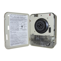
ET11x5CR–NEMA3Rindoor/outdoorlockablemetalenclosure•
ET11x5CPD82–NEMA3Rindoor/outdoorlockableimpactresis-•
tantpolycarbonateenclosurewithclearcover
Knockouts—Combination1/2-3/4inchsize,1onbackandeachside,
2onbottom
Wire Size—AWG#10through#18
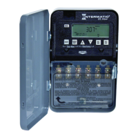
Installation and User Instructions
MODEL ET1100 Series
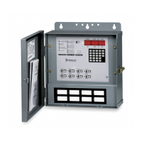
TheIntermaticET1100SeriesElectronic24-HourTimeSwitch
automaticallyswitchesloadstoapresetdailyschedulewithto-the-
minuteaccuracy.
UsetheET1100seriesasanON/OFFtimerinapplicationsrequir-
ing24-hourloadcontrolsuchaslighting,airconditioningsystems,
pumps,etc.EachloadoutputoftheTimeSwitchcansupportupto
14timedONand14timedOFFeventsperday.Theprogramcanbe
overriddenbypushingtheON/OFFloadoverridebutton(s).
TheET1100SeriesTimeSwitchisdesignedtodirectlyswitchtung-
stenorballastloadsuptoitsrating,andinductiveorresistiveloads
up to 30A at 120, 208, 240, or 277 VAC.
Specifications
With Battery
Carryover
Description
WARNING: Disconnect the
power to the Time Switch
and the loads before instal-
lation.
Removethemecha-1.
nismfromthecaseby
depressingthecatchat
thetopofthecaseand
pullingout,asshown.
CAUTION: Do not
touch circuit board
components since
static discharge could damage the microprocessor.
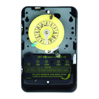
Setvoltageselectorfordesiredinputvoltage.2.
Thetimerisshippedwithvoltagesetfor120
VAC.Tooperateat208,240or277VAC,move
theselectorswitchtothedesiredsettingas
markedonthecircuitboard.SeelocationA in
Rear Viewaboveanddetailattheright.
ThetimerisshippedwithDST(DaylightSav-3.
ingTime)enabled.TodisableDST,insertajumperatlocation
markedDST.SeelocationB in Rear Viewabove
anddetailattheright.
ET1125C ONLY4. —Decidewhetheryouwant
tocontrolmultipleloadssimultaneously(SIM),
independently(IND),orwitha2-secondpulse
(PUL)(e.g.,forusewithmechanicallyheldcon-
tactorsorbellringingapplications),andmakesurethejumperis
positionedaccordingly.SeelocationB in Rear Viewaboveand
detailattheright.(TheunitisshippedwiththeloadssetforIND.)
Installation Instructions
Slide down
to remove
battery case
Snap out catch
Tilt top forward
Front View
Rear View
B
A
Electrical shock hazard. To avoid fire, shock, or death, disconnect all •
power before installing or servicing time switch or connected loads.
Follow local electrical and safety codes, National Electric Code (NEC) •
and Occupational Safety and Health Act Codes (OSHA).
If the power disconnect point is out of sight, lock it in the OFF position •
and tag it to prevent unexpected application of power.
This time switch must be grounded.•
Do not exceed maximum current carrying capacity.•
Always replace the plastic insulator covering the terminal before •
powering ON.
WARNING–Risk of Fire or Electric Shock