EasyManua.ls Logo

INVT GD20-004G-2 User Manual

INVT GD20-004G-2
140 pages
To Next Page IconTo Next Page
To Previous Page IconTo Previous Page
Page #103 background imageLoading...
Page #103 background image
Goodrive20 inverters
Communication protocol
102
END Lo END Hi=CR (0x0D), END Lo=LF (0x0A)
7.2.3.1 ASCII mode check (LRC Check)
Check code (LRC Check) is the value combined of address and data content result. For instance, the check
code of above 2.2.2 communication message is: 0x02+0x06+0x00+0x08+0x13+0x88=0xAB, then take the
compliment of 2=0x55. Below is a simple LRC calculation function for user reference (programed with C
language):
Static unsigned char
LRC(auchMsg,usDataLen)
unsigned char *auchMsg;
unsigned short usDataLen;
{
unsigned char uchLRC=0;
while(usDataLen--)
uchLRC+=*auchMsg++;
return((unsigned char)(~((char)uchLRC)));
}
7.3 Command code and communication data illustration
7.3.1 RTU mode
7.3.1.1 Command code:03H
03Hcorrespond to binary 0000 0011,read N wordsWord(the Max. continuous reading is 16 words)
Command code 03H means that if the master read data from the inverter, the reading number depends on
the “data number” in the command code. The Max. Continuous reading number is 16 and the parameter
address should be continuous. The byte length of every data is 2 (one word). The following command format
is illustrated by hex (a number with H” means hex) and one hex occupies one byte.
The command code is used to read the working stage of the inverter.
For example, read continuous 2 data content from0004H from the inverter with the address of 01H (read the
content of data address of 0004H and 0005H), the frame structure is as below:
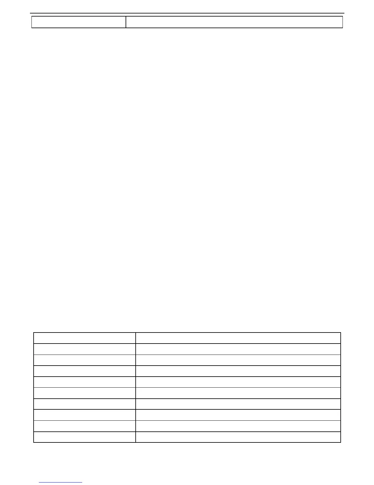
RTU master command message (from the master to the inverter)
START T1-T2-T3-T4
ADDR 01H
CMD 03H
High bit of the start address 00H
Low bit of the start address 04H
High bit of data number 00H
Low bit of data number 02H
CRC low bit 85H
CRC high bit CAH
END T1-T2-T3-T4
T1-T2-T3-T4 between START and END is to provide at least the time of 3.5 bytes as the leisure time and

Table of Contents

Question and Answer IconNeed help?

Do you have a question about the INVT GD20-004G-2 and is the answer not in the manual?

INVT GD20-004G-2 Specifications

General IconGeneral
Input Voltage3-phase 380V (-15%) - 440V (+10%)
Output Voltage0 - Input Voltage
Rated Current9A
Control ModeSVC, V/F
Protection FeaturesOver-current, Over-voltage, Under-voltage, Overload, Short circuit

Summary

Operation Manual

Safety Precautions

Safety Definition

Defines danger, warning, note, and qualified electrician terms for safety.

Warning Symbols

Lists symbols used for warnings and their meanings to prevent hazards.

Safety Guidelines

Provides essential safety rules for operating and handling the inverter.

Delivery and Installation Safety

Safety instructions for handling, installing, and moving the inverter.

Commissioning and Running Safety

Safety precautions during the startup, operation, and stopping of the inverter.

Maintenance and Component Replacement Safety

Safety guidelines for performing maintenance and replacing inverter components.

Product Overview

Product Specifications

Detailed technical specifications of the inverter's features and capabilities.

Rated Specifications

Lists electrical and performance ratings for various inverter models.

Installation Guidelines

Standard Wiring

Details on the standard wiring procedures for the main circuit.

Wiring of Terminals in Main Circuit

Step-by-step instructions for wiring the main circuit terminals.

Wiring Diagram of Control Circuit

Shows the schematic for connecting the control circuit.

Keypad Operation Procedure

Keypad Operation

Detailed instructions on how to operate the inverter using the keypad.

Modifying Function Codes

Procedure for changing inverter parameters and function codes.

Setting the Password

Steps to set or cancel the password for parameter protection.

Function Parameters

P00 Group: Basic Function Group

Parameters related to fundamental inverter functions like speed and run control.

P01 Group: Start-up and Stop Control

Parameters for controlling the inverter's start-up and stop sequences.

P02 Group: Motor Parameters

Parameters for configuring motor characteristics and protection.

P03 Group: Vector Control

Parameters specific to the vector control mode for precise motor operation.

P04 Group: SVPWM Control

Parameters for SVPWM control, including V/F curves and voltage settings.

P09 Group: PID Control

Parameters for setting up and tuning the PID control loop.

P11 Group: Protective Parameters

Parameters for various protection functions like phase loss and overvoltage.

Fault Tracking

Fault Solution Guide

Steps to identify, diagnose, and resolve inverter faults.

Fault Instruction and Solution Table

Detailed table listing fault codes, causes, and solutions.

Communication Protocol

Example of Writing and Reading

Practical examples demonstrating Modbus read and write operations.

Related product manuals