1
2 Power Supply
The specification of PLC built-in power and power for extension
modules is listed in the following table.
Normal startup and operation
Input: 90Vac, 100% output
The total power of outputs
5V/GND and 24V/GND ≤
10.4W. Max. output power:
24.8W (sum of all branches)
3 Digital Inputs & Outputs
3.1 Input Characteristic And Specification
The input characteristic and specs are shown as follows:
High-speed input
terminals X0~X7
Source mode or sink mode, set through s/s terminal
External circuit resistance < 400Ω
External circuit resistance > 24kΩ
X0~X7 have digital filtering function. Filtering time: 0,
8, 16, 32 or 64ms (selected through user programme)
Input terminals other than X0 ~ X7 are of hardware
filtering. Filtering time: about 10ms
X0~X7: high-speed counting, interrupt, and pulse
catching
X0 and X1: up to 50kHz counting frequency
X2~X5: up to 10kHz counting frequency
The sum of input frequency should be less than 60kHz
Only one common terminal: COM
The input terminal act as a counter has a limit over the maximum
frequency. Any frequency higher than that may result in incorrect
counting or abnormal system operation. Make sure that the input
terminal arrangement is reasonable and external sensors used are
proper.
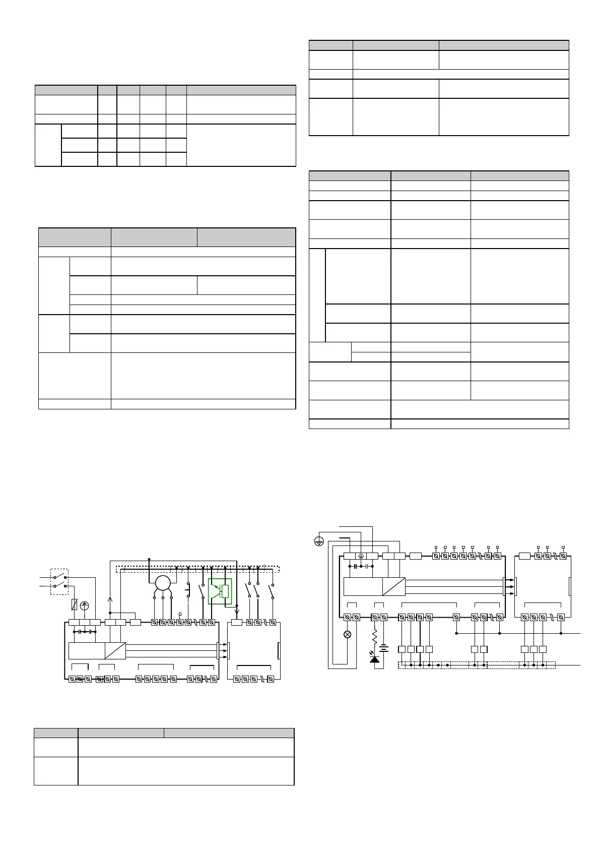
Input connection example
The following diagram shows an example of IVC1L-1614MAR in
connection with an IVC1-0808ENR, which realizes simple positioning
control. The positioning signals from the PG are input through high
speed counting terminals X0 and X1, the limit switch signals that
require high-speed response can be input through high-speed
terminals X2 ~ X7. Other user signals can be input through any other
input terminals.
3.2 Output Characteristic And Specification
The following table shows the relay output and transistor output.
When output state is ON, the circuit is closed; OFF, open
Divided into multiple groups, each with a common terminal
COMn, suitable for control circuits with different potentials.
All common terminals are isolated from each other
220Vac; 24Vdc, no
polarity requirement
24Vdc, correct polarity required
Accord with output electric specs (see following Table )
High driving voltage,
large current
Small driving current, high frequency,
long lifespan
Loads with low action
frequency such as
intermediate relay,
contactor coil, and LEDs
Loads with high frequency and long
life, such as control servoamplifier
and electromagnet that action
frequently
The electric specs of outputs is shown in the following table.
Transistor output terminal
Relay output contacts
closed, LED on
LED is on when optical
coupler is driven
Leakage current of
open circuit
2A/1 point;
8A/4 points, using a
COM
8A/8 points, using a
COM
Y0/Y1/ Y2/Y3: 0.3A/1 point.
Others: 0.3A/1 point, 0.8A/4
point, 1.2A/6 point, 1.6A/8
point. Above 8 points, total
current increases 0.1A at
each point increase
Y0/Y1/ Y2/Y3: 7.2W/24Vdc
Others: 12W/24Vdc
Y0/Y1/ Y2/Y3: 0.9W/24Vdc
Others: 1.5W/24Vdc
Y0/Y1/ Y2/Y3: 10us
Others: 0.5ms
Y0, Y1 max. output
frequency
Y2, Y3 max. output
frequency
Y0/ Y1-COM0; Y2/Y3-COM1. After Y4, Max 8
terminals use one isolated common terminal
Output connection example
The following diagram shows an example of IVC1L-1614MAR in
connection with an IVC1-0808ENR. Different output groups can be
connected to different signal circuits with different voltages. Some (like
Y0-COM0) are connected to the 24Vdc circuit powered by local
24V-COM, some (like Y2-COM1) are connected to the 5Vdc low
voltage signal circuit, and others (like Y4~Y7) are connected to the
220Vac voltage signal circuit.
Use terminal block to
conncet common terminals
Various low voltage control circuits
220Vac control load circuits
4 Communication Port
IVC1L series PLC basic module has three serial asynchronous
communication ports: PORT0 and PORT1、PORT2. Supported baud
rates:
The mode selection switch determines the communication protocol.

 Loading...