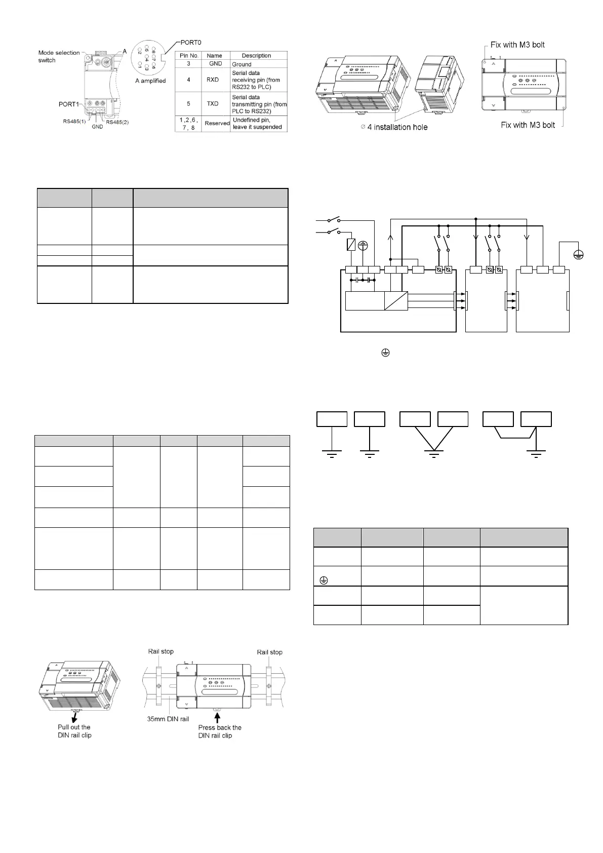
2
As a terminal dedicated to user programming, PORT0 can be
converted to programming protocol through the mode selection switch.
The relationship between PLC operation status and the protocol used
by PORT0 is shown in the following table.
Mode selection
switch position
Programming protocol, or Modbus protocol,
or free-port protocol, or N: N network
protocol, as determined by user program and
system configuration
Converted to programming protocol
If the system configuration of user program is
free-port protocol, it converts to programming
protocol automatically after stop; or system
protocol keeps unchanged
PORT1、PORT2 are ideal for connection with equipment that can
communicate (such as inverters). With Modbus protocol or RS485
terminal free protocol, it can control multiple devices through the
network. Its terminals are fixed with screws. You can use a shielded
twisted-pair as the signal cable to connect communication ports by
yourself.
5 Installation
PLC is applicable to Installation category II, Pollution degree 2.
5.1 Installation Dimensions
IVC1L-0806MAR
、
IVC1L-0806MAT
IVC1L-1208MAR
、
IVC1L-1208MAT
IVC1L-1410MAR
、
IVC1L-1410MAT
、
IVC1L-1614MAR
、
IVC1L-1614MAT
IVC1L-2416MAR
、
IVC1L-2416MAT
、
IVC1L-1614MAR1
、
IVC1L-1614MAT1
、
IVC1L-3624MAR
、
IVC1L-3624MAT
5.2 Installation Method
DIN rail mounting
Generally you can mount the PLC onto a 35mm-wide rail (DIN), as
shown in the following figure.
Screw fixing
Fixing the PLC with screws can stand greater shock than DIN rail
mounting. Use M3 screws through the mounting holes on PLC
enclosure to fix the PLC onto the backboard of the electric cabinet, as
shown in the following figure.
5.3 Cable Connection And Specification
Connecting power cable and grounding cable
The connection of AC power and auxiliary power is demonstrated in the
following figure.
We suggest you wire a protection circuit at the power supply input
terminal.See the figure below.
Connect the PLC terminal to the grounding electrode. To ensure
reliable grounding cable connection, which makes the equipment safer
and protects it from EMI.use AWG12~16 cable, and make the cable as
short as possible. Use independent grounding. Avoid sharing route with
the grounding cable of other equipment (particularly those with strong
EMI). See the following figure.
Cable specification
When wiring a PLC, use multi-strand copper wire and ready-made
insulated terminals to ensure the quality. The recommended model and
the cross-sectional area of the cable are shown in the following table.
Cable lug and
heat-shrink tube
H1.5/14 round insulated
lug, or tinned cable lug
H2.0/14 round insulated
lug, or tinned cable end
UT1-3 or OT1-3
solderless lug
Φ3 or Φ
4
heat shrinkable
tube
Fix the prepared cable head onto the PLC terminals with screws.
Fastening torque: 0.5~0.8Nm.
The recommended cable processing-method is shown in the following
figure.
PLC PLC
Other
equipment
Other
equipment
PLC
Other
equipment
Best Good
Bad

 Loading...