8.1.6 CAN bus cables
recommended specifications
Section 2 x 0.50 mm2 (46 AWG) power supply
2 x 0.25 mm
2
(23 AWG) data line
Type Two twisted pairs (power supply and data)
and one drain wire (or shield)
Connectors 5-pole M12, see "Connectors M12 CAN bus"
on page83
Connectors shall be type 3 (raintight)
Impedance 120 Ω ±12 Ω (f = 1 MHz)
Shield Shield with twisted wires in tin-plated
copper. To be connected to ground circuit
on the power supply terminal block of the
control unit.
Standards Cables shall be listed in accordance with
application as described in the National
Electrical Code, NFPA 70, and in the
Canadian Electrical Code, C22.1.
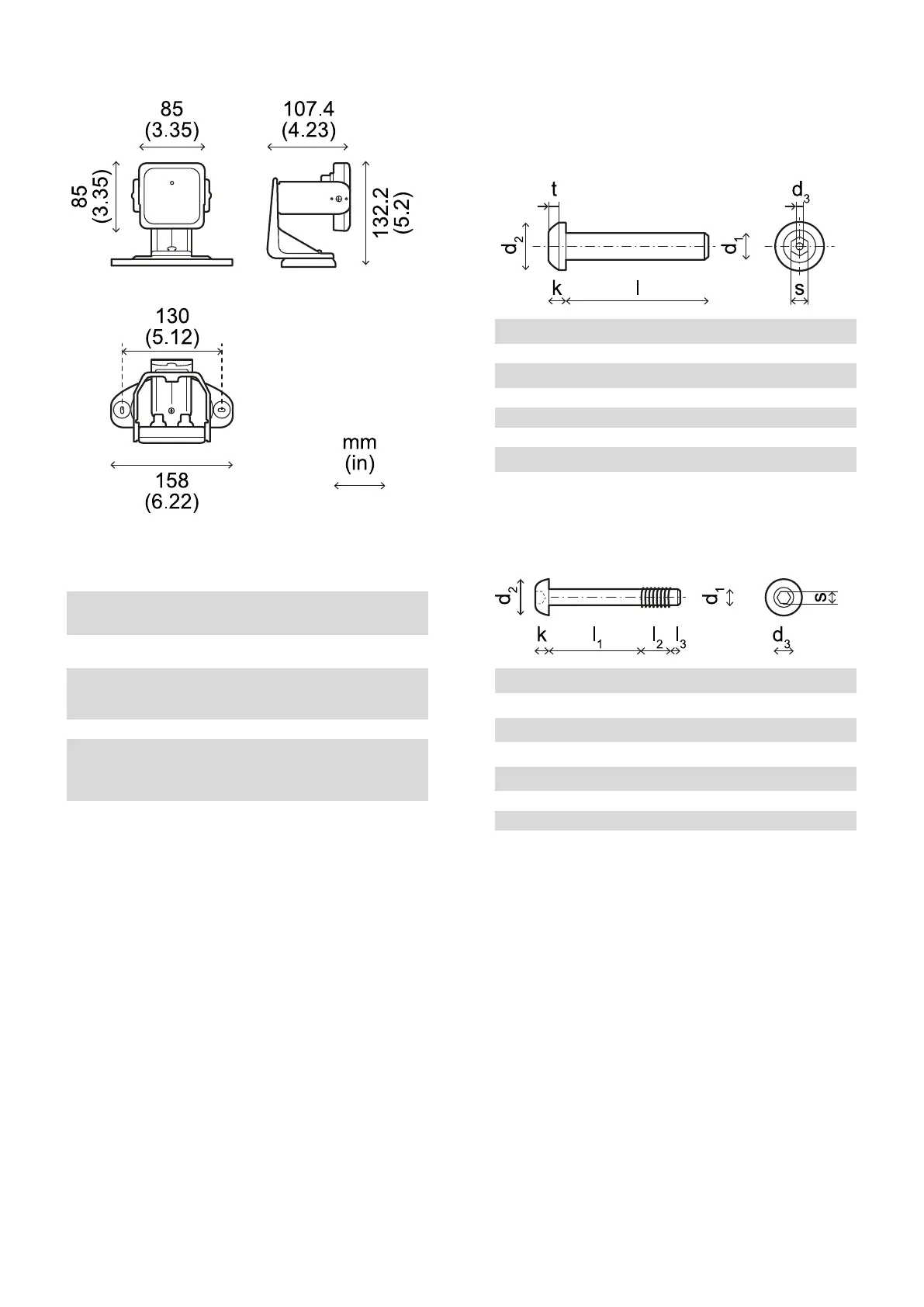
8.1.7 Tamper-proof screws
specifications
Pin Hex button head security screw
d
1
M4
l 10 mm (0.39 in)
d
2
7.6 mm (0.30 in)
k 2.2 mm (0.09 in)
t min 1.3 mm (0.05 in)
s 2.5 mm (0.10 in)
d
3
max 1.1 mm (0.04 in)
8.1.8 Non tamper-proof screws
specifications
Hex button head screw
d
1
M4
l
1
19 mm (0.74 in)
l
2
6 mm (0.23 in)
l
3
2 mm (0.07 in)
d
2
7.6 mm (0.30 in)
k 3 mm (0.11 in)
s 2.5 mm (0.10 in)
d
3
4 mm (0.15 in)
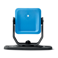
8. Technical references
SBV System Series| Instruction manual v1.2 DEC 2021|SAF-UM-SBVBus-en-v1.2|© 2021 Inxpect SpA
81
 Loading...