Installation
6 720 643 409 (2010/03)
33
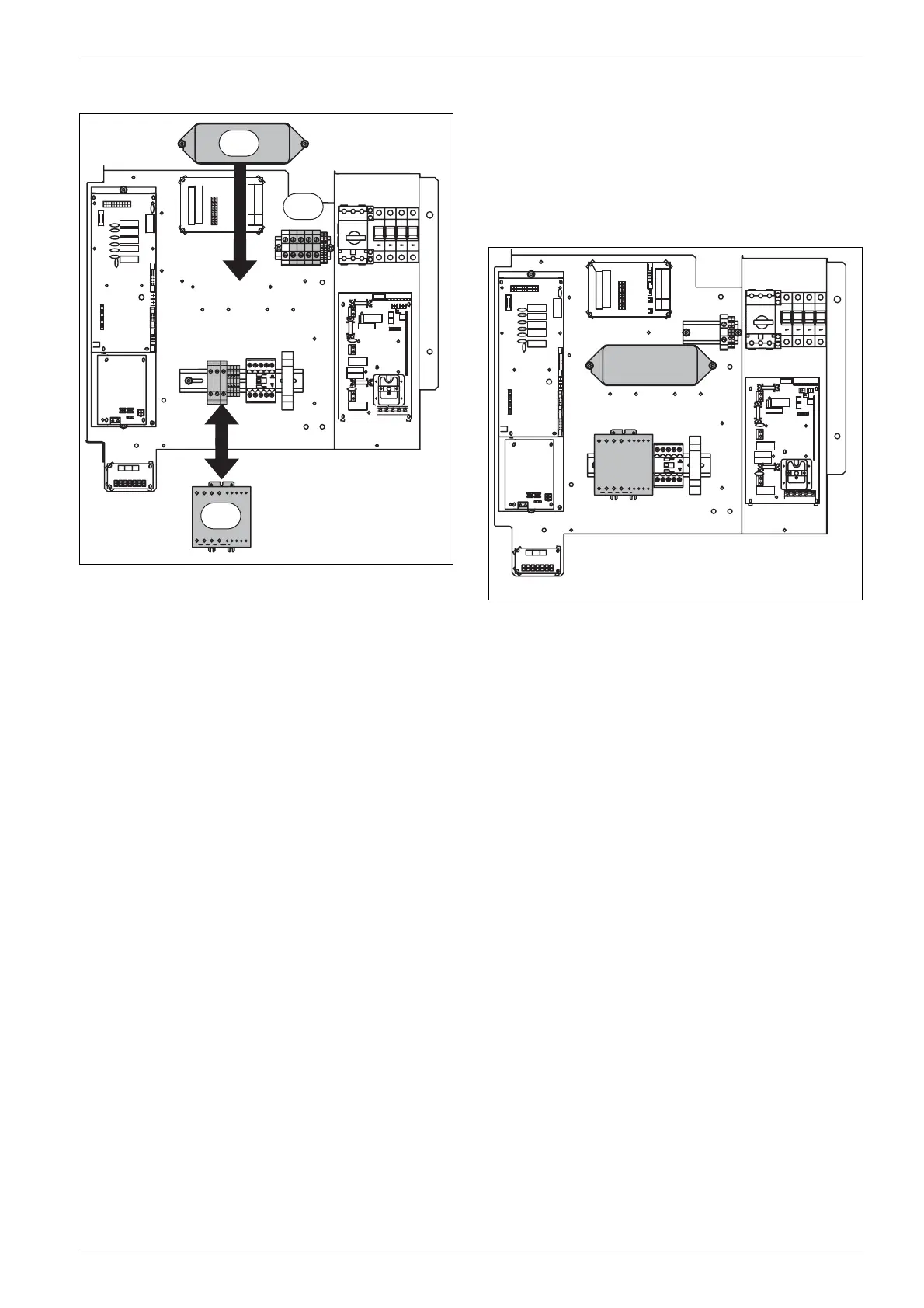
Fig. 30 Installing soft starter and EMC filter
1. Check that the power cables are in the following
order on the terminal blocks: L1 black, L2 brown, L3
grey. Disconnect the cables and remove the terminal
blocks.
B Remove the remaining terminal blocks, 22, 23, 24 and
A1 and A2 from the mounting rail and put them
carefully to one side with the cables still connected.
Then install the soft starter on the rail.
B Connect the power cables to the soft starter as they
were previously connected on each side: L1 black, L2
brown, L3 grey.
B Remove the remaining cables from the terminal
blocks and connect the soft starter as numbered. The
cables must be connected to the soft starter on the
same connector numbers as the previous terminal
blocks were installed on (note that a terminal block
can have two cables connected together). All cables
are now reconnected.
B Carefully remove the cover of the soft starter and set
the rotary potentiometers to the values given in the
documentation provided with the soft starter. Then
reinstall the cover.
2. Remove the marked terminal blocks. (N, L1, L2, L3)
3. Install the EMC filter in the existing holes so that Line
in is on the right hand side and Load out on the left.
B Connect the cables to the EMC filter to the same
connection numbers as the previous terminal blocks
were mounted. The cables were connected to the
EMC filter load side marked Load out.
B Install the incoming power supply for the heat pump
on the EMC filter side marked Line in.
Fig. 31 Install the soft starter and filter.
9.10 Switching electric element from 3kW
to 6kW.
B Disconnect the three grey cables on contactor K2.
B Insulate them.
B Uninsulate the three white cables.
B Connect the three white cables where the grey cables
were connected (the order does not matter).
6 720 641 855-21.1I
2
3
1
6 720 641 855-22.1I
 Loading...


