46
Terminal card
Incoming supply
3 x400V + N + PE
Compressor
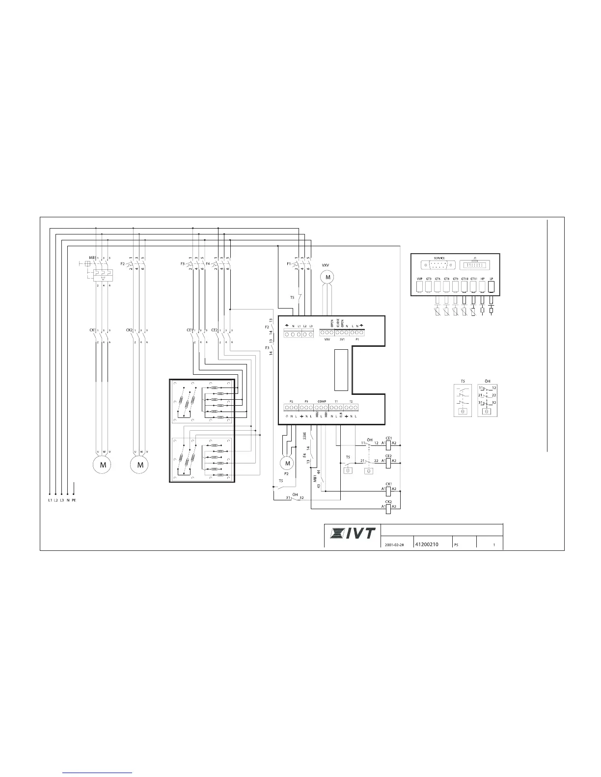
Circuit diagram, Greenline E20
MB 1: Motor cutout compressor
CK 1: Contactor compressor
CK 2: Contactor, heat transfer fluid pump
CE 1: Contactor electric heater Step 1
CE 2: Contactor electric heater Step 2
F 1: Circuit-breaker heat pump
F 2: Circuit breaker electric water heater step 1
F 3: Circuit breaker electric water heater step 2
F 4: Circuit breaker, heat transfer fluid pump
TS: Thermostat operation (manual)
ÖH: Overheating protection
SSM: Thermal protection heat transfer fluid pump
G3 (P3) Heat
transfer fluid
pump
Electric water heater 18 kW
(6.75 kW + 11.25 kW)
Sensor board
Internal couplings
Low pressure switch
Pressure switch high
HTF (coll) out
HTF (coll) in
Heat trfr fld in
Heat trfr fld out
Compressor
CIRCUIT DIAGRAM
IVT GREENLINE E20
DATE DRAWING NUMBER DRAWN BY PAGE
 Loading...