3
For wall mounting please use the screws enclosed.
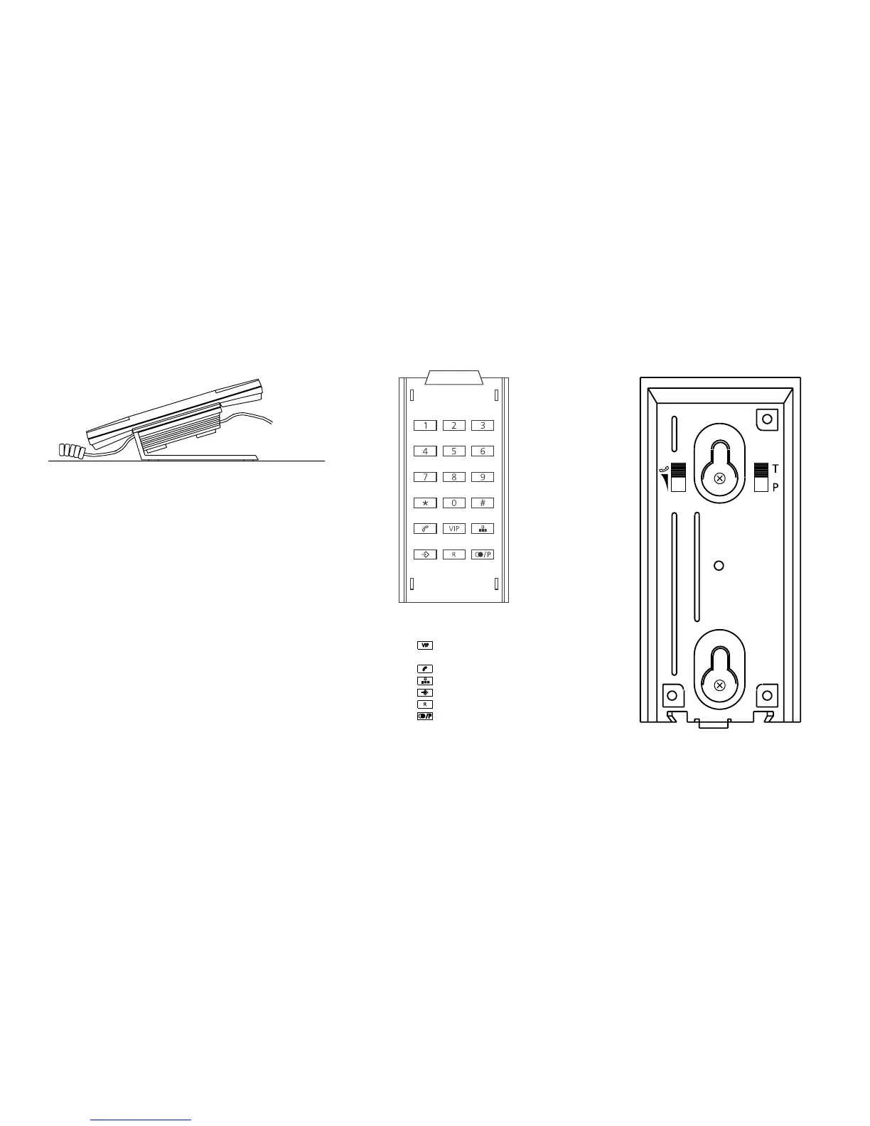
Mount the screws according to the distance shown in fig. 4 below.
(6 mm drill for plugs).
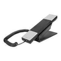
Fig. 4.
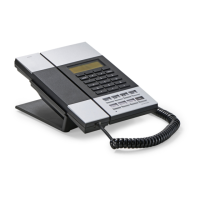
Fig. 2.
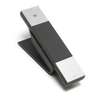
Fig. 1.
Ringing melody and volume
1. Melody A Low
2. Melody A Normal
3. Melody A High
4. Melody B Low
5. Melody B Normal
6. Melody B High
7. Melody C Low
8. Melody C Normal
9. Melody C High
0. OFF OFF
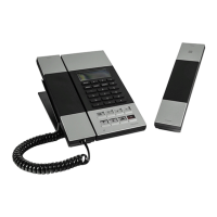
Fig. 3.
Description
1. Base (fig. 1)
2. Numerical keys (fig. 2)
3. Functional keys (fig. 2)
4. Select tone/pulse
at the rear side of the base - T/P (fig. 4)
5. Fittings for wall mounting (fig. 4)
6. Coiled cord (fig. 1)
7. Table stand (fig. 1)
8. Microphone-switch (handset - MUTE)
9. Receiver volume control (HI/LOW)
at the rear side of the base (fig. 4)
Features
a.
one-touch number.
b. Ten two-touch numbers (0-9).
c.
Hook switch key.
d.
For storing and dialling numbers (0-9).
e.
For storing numbers (VIP, 0-9).
f.
(for switchboard and special services).
g.
For redial or pause.
h. Mute (on the handset).
i. Table / Wall mounting.
 Loading...