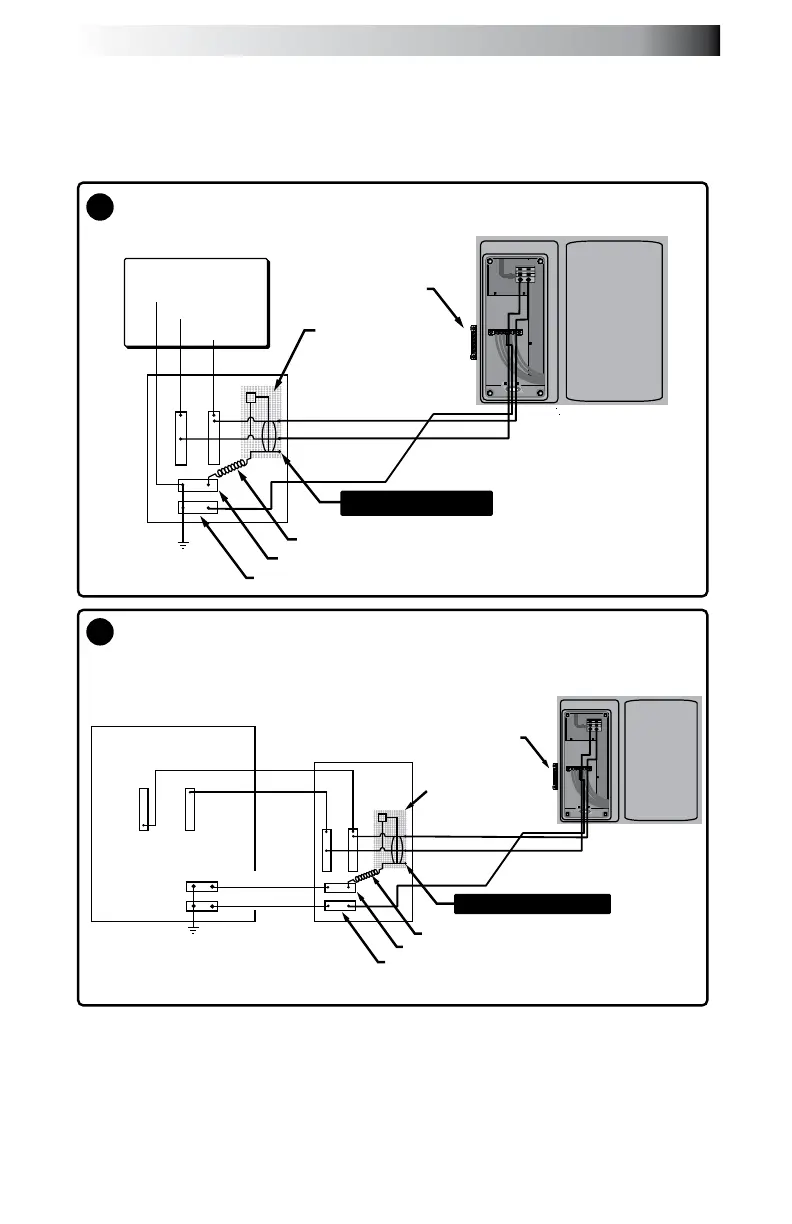
Red (L2)
Pigtail
Neutral Bus
Ground
Black (L1)
Green
Main
Service
Panel
with
GFCI
2-Pole
GFCI
Breaker
Ground/Bonding Lug**
2-Pole Circuit Breaker with 2-Wire Grounded Load Connection
(3 Wires to Hot Tub, 2-Hot (L1-L2), 1-Ground)
White (N)
Black (L1)
Red (L2)
240 VAC
No Load Neutral Wire
Note: service disconnect not
shown in this diagram.
The control box TB1 terminal
position varies between models.
Red (L2)
Red (L2)
Pigtail
Neutral Bus
Ground
Black (L1)
Black (L1)
Green
GFCI Sub Panel*
Main Panel*
2-Pole
GFCI
Breaker
Ground/Bonding Lug**
No Load Neutral Wire
Main Panel with Secondary GFCI Shut-Off Box Using a
2-Pole GFCI Breaker with 2-Wire Grounded Connection
(3 Wires to Hot Tub, 2-Hot (L1-L2), 1-Ground)
White (N)
Green (Ground)
*GFCI Sub Panel commonly
used when recommended GFCI
does not install in Main Panel.
Note: service disconnect not
shown in this diagram.
The control box TB1 terminal
position varies between models.
B
A
240 VAC
18.0 Typical Spa Wiring Diagrams
 Loading...