favorite recordings. Recordings of solo voices are recom
mended because most listeners are able to perceive a voice
that is improperly balanced much more easily than an
orchestra presented with the same degree of imbalance.
During the evaluation, amplifier tone controls should be
set at their middle (typically referred to as "flat”) position
and the mode or equivalent selector switch in the monaural
(L & R) position. The balance control should be placed full
left or full right; and initial network adjustments made to
that channel only. After adjustment, listen a short while then
move the balance control to the opposite extreme. This will
provide an instant comparison between the adjusted channel
and the normal channel. The normal channel will serve as
an excellent point of reference.
Actual adjustments should proceed as follows:
1. Check to see that the midrange control is switched to the
MED position. Rotate the high frequency control to the
extreme left of its travel. This attenuates high frequency
output so that the ear hears only the balance between the
low frequency and midrange loudspeakers.
2. Pay particular attention to the smoothness and natural
ness of the voice. If it sounds too bright and over
emphasized, switch the control to the MIN (minimum)
position. If it sounds distant or slightly muffled, switch the
control to MAX (maximum) position.
3. When the midrange dividing network has been satisfac
torily adjusted, gradually increase the setting of the high
frequency control until a pleasing overall balance has been
achieved. In addition to voice, recordings having bells,
cymbals and triangles are also useful for this test.
After each adjustment, listen to two or three different
recordings. This gives a broader base on which to make
judgments as to the best setting of the controls. When final
settings have been determined on one channel, merely dupli
cate these settings on the remaining channel. Compensation
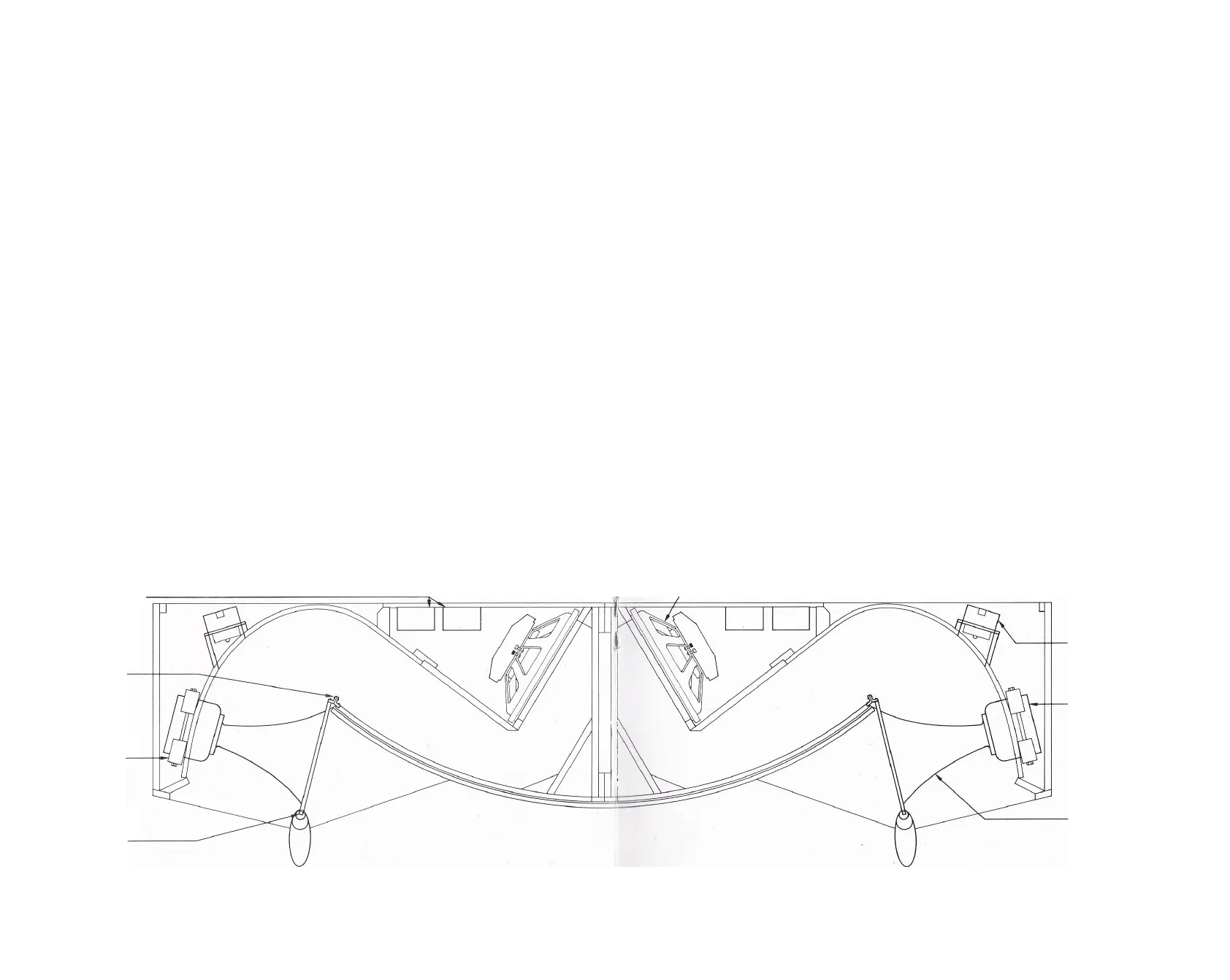
Position of
Dividing Network
Inner Mounting
Brackets for
H5038P Horn
Clamp Assembly
for 376 Driver
Outer Mounting
Bracket for
H5038P Horn
for differences in individual recordings should be made
using the tone controls on the amplifier or receiver.
Mounting positions of individual components are shown COMPONENT REMOVAL
in the illustration below. If it should become necessary to
remove the loudspeaker system components for testing or
repair, disconnect the Paragon from the amplifier and pro
ceed as outlined below.
LOW FREQUENCY Remove the 16 Phillips-head screws from
the panel at the rear of the enclosure. Carefully tilt the panel
outward for access to the low frequency driver and detach
the wire leads from the driver. Holding the loudspeaker
firmly, remove the four screws that attach it to the baffle
board. If the loudspeaker gasket adheres to the baffle, gently
separate it using a sturdy, broad-bladed tool such as a putty
knife. In severe cases, a large screwdriver may be required.
Take care to avoid unnecessarily damaging the gasket.
MIDRANGE DRIVER AND HORN Remove the upper section
of the sculptured front leg by firmly pulling it upward. Next,
unscrew the two Phillips-head machine screws that hold the
front edge of the horn mouth to the mounting bracket.
Remove the two Phillips-head machine screws which attach
the rear edge of the horn mouth to the rear mounting brack
et. Using a 1/8" Allen wrench, remove the four socket-head
machine screws which fasten the midrange driver to the
horn. Detach the wire leads located at the rear of the driver.
Loosen the two 9/16" square nuts retaining the clamp as
sembly which holds the driver in place. The driver can now
be removed by pulling it forward. When reinstalling the
driver, make certain that its input terminals face toward the
rear of the enclosure before mounting the horn in place. Do
not clamp the driver into position until it has been attached
to the horn and the front horn flanges are assembled to their
respective brackets.
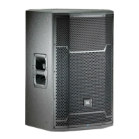
LE15H
Low Frequency
Loudspeaker
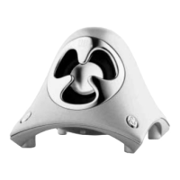
075
High Frequency
Ring Radiator
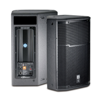
376
Midrange
Compression Driver
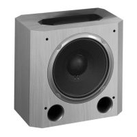
H5038P
Exponential Horn
 Loading...