06 - Body and Framework
03 - Chassis
36 - Upper Crossmember
06 - 10 9813/5350-2 06 - 10
36 - Upper Crossmember
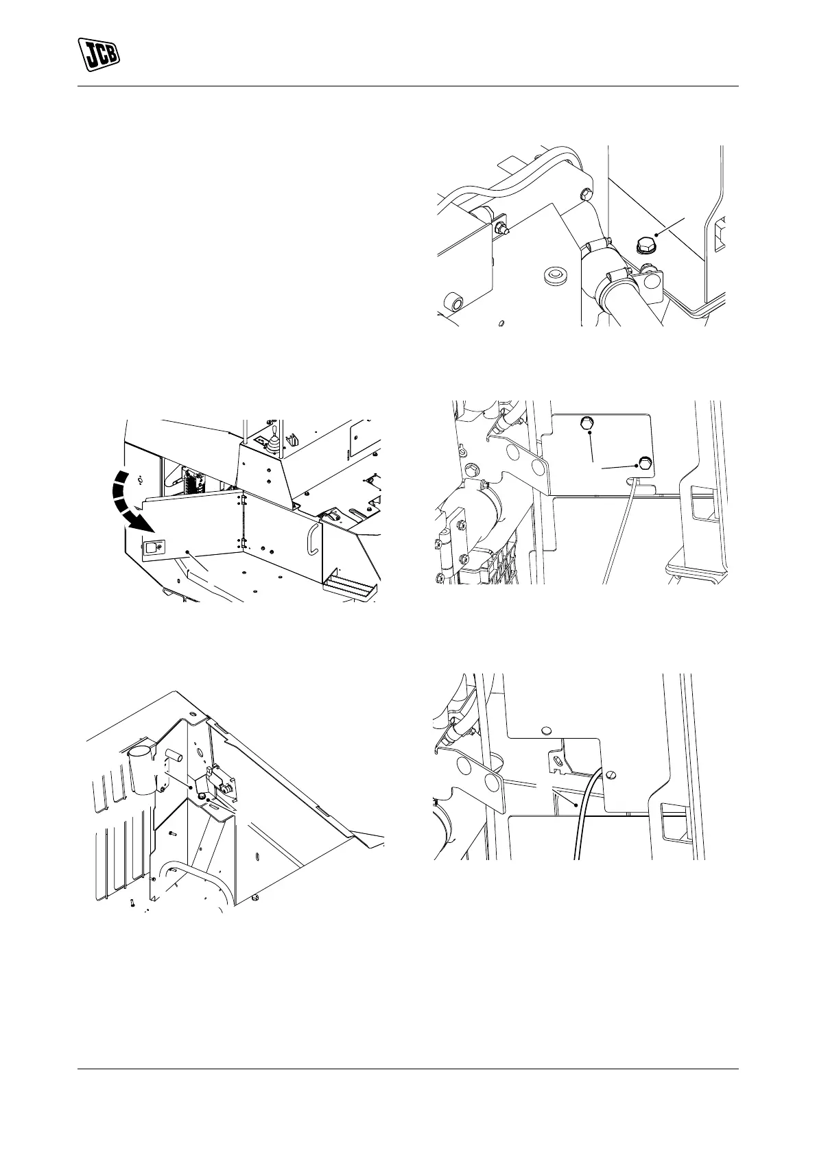
Remove and Install
(For: 10TFT, 9TFT)
Remove
1. Make the machine safe.
Refer to: PIL 01-03-27.
2. Isolate the battery.
Refer to: PIL 33-03.
3. Open the side access panel.
Figure 13.
A Side access panel
4. Remove the top bolts 1 from the engine
compartment cover.
Figure 14.
B Bolts 1
5. Remove the bolts 2 from the upper
crossmember.
Figure 15.
C Bolts 2
6. Remove the bolts 3 from the reverse alarm cover.
Figure 16.
D Bolts 3
7. Disconnect the reverse alarm electrical
connector.
Figure 17.
E Electrical connector
8. Support the upper crossmember with suitable
lifting equipment.
9. Remove the upper crossmember from the
machine.
 Loading...