About the Product
Operator Station
16 9811/9500-4 16
Operator Station
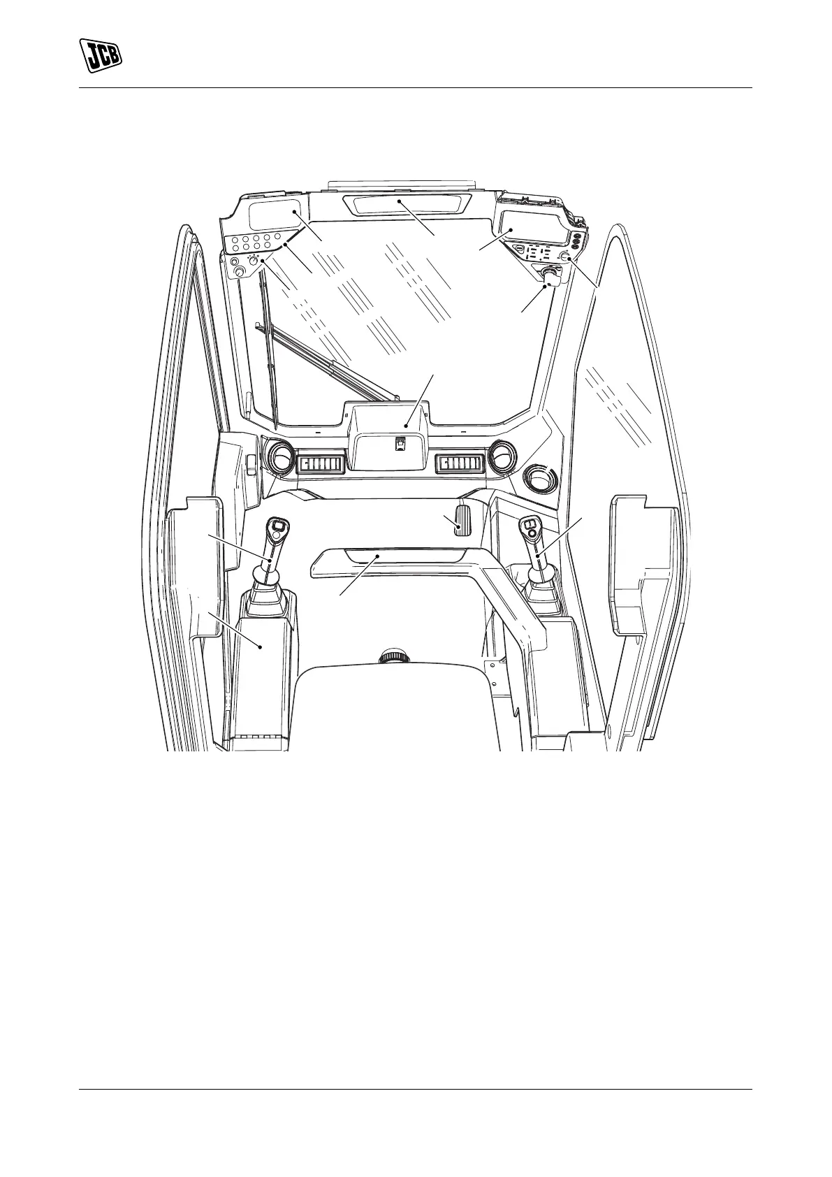
Component Locations
Figure 11.
A Left armrest (contains 12V accessory socket),
Refer to: Operation > Safety Equipment
(Page 53).
B Right interlock bar,Refer to: Operation > Safety
Equipment (Page 53).
C Left joystick control lever, Refer to: Operation >
Drive Controls (Page 55).
D Right joystick control Lever, Refer to: Operation
> Operating Levers/Pedals (Page 84).
E Left switch panel, Refer to: Operation >
Instruments > General (Page 63).
F Radio, Refer to: Operation > Radio > General
(Page 95).
G Front panel, Refer to: About the Product >
Console Switches (Page 17).
H Cab HVAC (Heating Ventilation Air
Conditioning), (optional)Refer to: Operation
> Heating, Ventilating and Air-Conditioning
(HVAC) (Page 93).
J Instruments, Refer to: Operation > Instruments
(Page 63).
K Hand throttle, Refer to: Operation > Safety
Equipment (Page 53).
L Ignition switch, Refer to: About the Product
> Interior Switches > Ignition Switch
(Page 18).
P Foot throttle control (optional), Refer to:
Operation > Drive Controls (Page 55).
Q Interior rear view mirror, Refer to: Operation >
Mirrors > General (Page 43).
 Loading...