About the Product
Operator Station
16 9821/7850-4 16
Operator Station
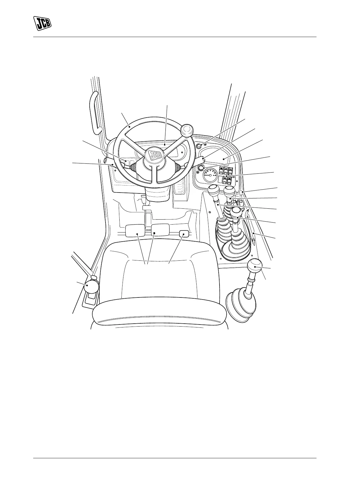
Component Locations
Figure 11.
A Steering wheelRefer to: Steering Wheel
(Page 50).
B Warning clusterRefer to: Instruments
(Page 53).
C Auxiliary socket D Multi-purpose switch Refer to: Drive Controls
(Page 50).
E Instrument panelRefer to: Instruments
(Page 53).
F Ignition switchRefer to: Introduction (Page 1).
G Console switchesRefer to: Introduction
(Page 1).
H Stabiliser controlsRefer to: Operation
(Page 21).
J Carriage controls Refer to: Operating Levers/
Pedals (Page 60).
K Boom controlsRefer to: Operating Levers/
Pedals (Page 60).
L Auxiliary controlsRefer to: Operating Levers/
Pedals (Page 60).
M Gear leverRefer to: Drive Controls
(Page 50).
N Accelerator pedalRefer to: Drive Controls
(Page 50).
P Service brake pedalRefer to: Service Brake
Pedal (Page 50).
Q Park brakeRefer to: Park Brake (Page 50). R Transmission lever and gear selectionRefer to:
Drive Controls (Page 50).
S Console switchesRefer to: Console Switches
(Page 19).
T Control lock pinRefer to: Safety Equipment
(Page 49).
 Loading...