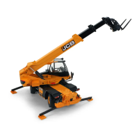
Chassis Levelling (Sway) Operation
Vehicle Steer Mode
Engine Compartment
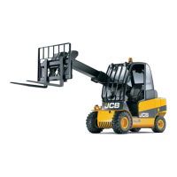
Double Lever Control
Stabilizer Controls
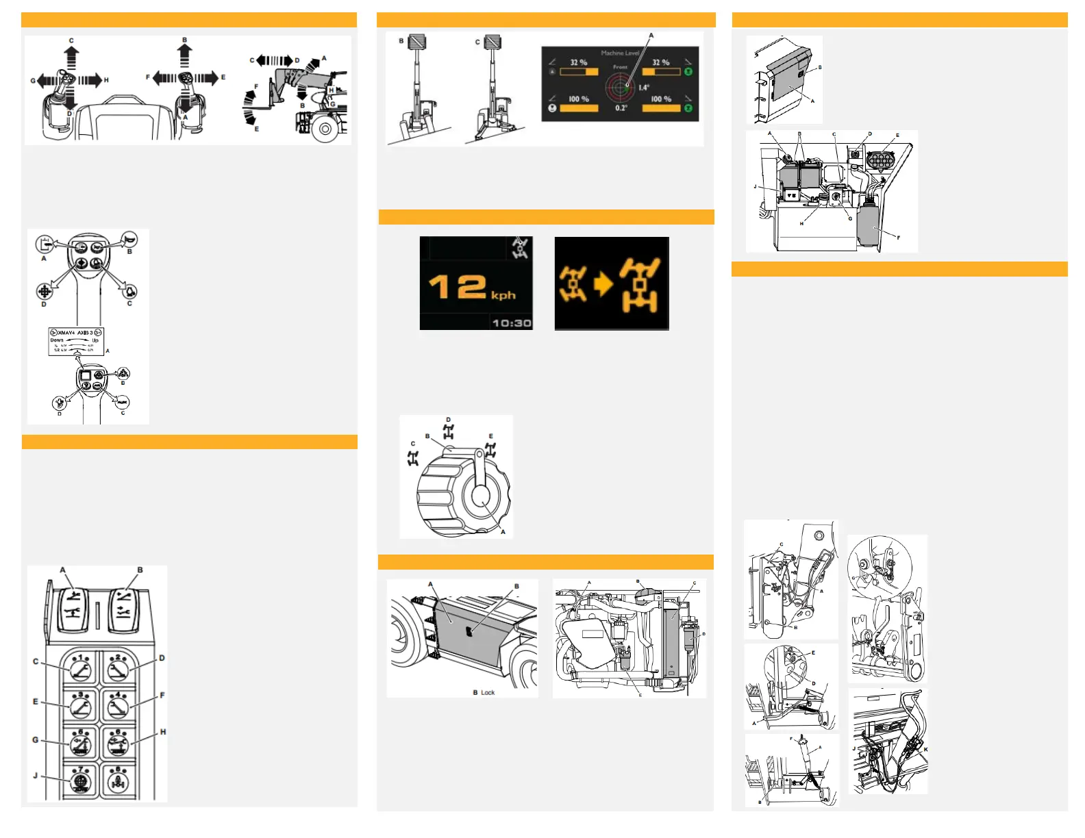
Connecting Attachments
A. Boom Raise
B. Boom Lower
C. Boom Extend
D. Boom Retract
E. Carriage Tilt Forward
F. Carriage Tilt Back
G. Slew counterclockwise
H. Slew clockwise
An icon on the LCD (Liquid Crystal Display) Screen tells you what
steer mode the machine is in. Information on the icons and the
notification screens when changing between steer modes is contained
in the LCD screen operation instructions.
A. Engine Oil Dipstick
B. Coolant Expansion Tank
C. Radiator
D. Water Separator
E. Fuel Filter
Battery Compartment
Right Hand Joystick
A. Restore full hydraulic service speed
B. Horn
C. One touch engine idle
D. Envelope override
A. Auxiliary hydraulics control
B. Speed profile quick selection
C. Auxiliary service change over
button
D. Controls enable
Left Hand Joystick
A. Raise/lower outrigger switch
B. Extend/retract outrigger switch
C. Left front outrigger selection
button
D. Right front outrigger selection
button
E. Left rear outrigger selection
button
F. Right rear outrigger selection
button
G. Outriggers auto deploy and level
selection
H. Outriggers auto stow selection
button
J. Outriggers auto level selection
button
Auto Deploy
Press and hold the auto deploy function button on the keypad
for 2s. All outriggers which are not already in
the deployed state are automatically selected and fully
extended. When all outriggers are 100% extended they
are then lowered until all are deployed. Then the machine is
then automatically levelled to +/- 0.5°.
A. Machine level indicator status
B. Chassis level
C. Outrigger's level
A. Rotary knob
B. 4-Wheel steer
C. 2-Wheel steer
D. Crab steer
A. Engine Cover
B. Lock
A. Hydraulic filler cap
B. Batteries
C. Primary fuse
D. DEF tank filler cap
E. Air Filter
F. DEF Tank
G. Battery Isolator
H. Fuel filler cap
A. Battery Cover
B. Lock
1. Lower the manual locking lever to disengage the carriage lock pins.
2. Use the controls to line up the carriage with the attachment and just
below the hook plates, located on the platform.
3. Using the boom controls, engage the support bar on the carriage into the
hook plates on the attachment.
4. Make sure that both hook plates are engaged equally.
5. Make sure that the forward/reverse lever is set to neutral, and that the
park brake is on.
6. Stop the engine and remove the starter key.
7. At the carriage, operate the manual locking lever to engage the lock pins.
8. Make sure that the locking pins are fully engaged.
9. If a second person is to do this job, keep your hands and feet away from
the controls until he is clear of the machine.
10. Secure the manual locking lever with a locking pin.
11. If the machine is fitted with the optional carriage, make sure that the
locking pin is securely fitted.
12. If the platform is of the slew-type: attach the hydraulic hoses to the
auxiliary circuit connections, feed the hoses into their guides and retain
with the locking pins.
13. Connect the electrical connector.
A. Manual locking lever
B. Lock pins
C. Hook plates
D. Attachment
E. Carriage
F. Locking pin
G. Locking Pin
J. Locking pins
K. Hydraulic hoses
 Loading...