제품의설명
DESCRIPTION
설치
1.앰프의파워코드를ACOUTLET으로부터뽑으십시오.
파워앰프의faultdetection모듈은출력레벨2VRMS(70or100Vline)
에서20KHz의주파수에의해서앰프의작동상태를파악하고,스피커
라인의접속끊김을체크합니다.
Blockdiagram에서볼수있듯이,20KHz(2VRMS)는스피커케이블을통
해서detection모듈로전달이되며앰프의출력상에서다른signal과섞
이게된다.그리고detection모듈은fault를체크하는filter를통해서20
KHz주파수를감시합니다.
2.FD-200SLOT의BLANKPANEL을제거한다음콘넥터(AN601)가
묶인케이블타이를풀어주십시오.
3.FD-200모듈의CN601에콘넥터(AN601)를연결한다음FD-200
보드상의SW1을ON위치로설정하십시오.
5.FD-200을후면판넬에부착하십시오.
6.앰프의출력터미널의COM단자와100V단자를FD-200의COM단자
와HOT단자에각각결선하십시오.
7.FD-200의릴레이접점을FS-3381(FAULTSTAND-BYAMPSWITCHER)
1.DigitalPortableMultimeter를AC전압측정레인지에설정하고,측정리
드를파워앰프의COM과70V/100V단자에연결하시오.
"OSCLEVEL"볼륨을조정하여전압계가2VacRMS(20KHz)가되도록설
정하십시오.
2.DigitalPortableMultimeter를AC전압측정레인지에설정하고,측정리
드를"TEST"콘넥터에연결하십시오.
"Sensitivity"볼륨을조정하여전압계가2VacRMS(20KHz)가되도록설
정하십시오.
제거되었던PGM과PRIORITY오디오입력단자를다시연결하십시오.
의릴레이접점입력단자와결선하십시오.
파워앰프의PGM과PRIORITY입력스크류터미널을뽑으십시오.
Ensure amplifier to be adjusted in not being used, I.e. Unplug
the PGM and PRIORITY input screw terminals.
INSTALLATION
1. Unplug the power cable from a AC outlet.
2. Remove the rear mounted blank panel, and mount the
FD-200 in the resultant hole using screws supplied with the
module.
3.
of CN601 on the FD-200.
4. Set the switch "FD-200" of FD-200 ON/OFF switch on the
rear panel of amplifier.
5. Screw FD-200 on the panel.
7. Connect relay contact of FD-200 to the input terminal of relay
contact of FS-3381. (FAULT STAND-BY AMP SWITCH)
6. Connect "COM" of AMP output terminal and 100V terminal
to the "COM" and "HOT".
CALIBRATING FD-200 ON POWER AMPLIFIERS
파워앰프설치후FD-200조정방법.
4.앰프의후면판넬의FD-200ON/OFF스위치를FD-200위치로설정
하여주십시오.
1. Set Digital Portable Multimeter to measure AC voltage and
Confirm output of power amplifier is 2Vac RMS at 20KHz.
Adjust "OSC LEVEL" potentiometer(VR602), If necessary.
2. Set Digital Portable Multimeter to measure AC voltage and
connect "TEST" connector. Confirm reading of 2Vac RMS at
주의:Digitalportablemultimeter는 20KHz 주파수를측정할
수있는정밀한계측기를사용하십시오.
Note : Use accuracy Digital portable multimeter which has
FQ test range.
The fault detection module of power amplifier checks operating
conditions of amplifier and disconnection of speaker wiring by
giving out the sine wave of 20KHz at an output level of 2V RMS
(at 70 or 100V line).
As the block diagram shows, the sine wave of 20KHz(2V RMS)
deliverd to the detection module though speaker cables and
the detection module detects only the sine wave of 20KHz
through a filter to check a fault.
Set "ON" position SW1 on the FD-200 module after connection
connect across power amplifier COM and 70V/100V terminals
20KHz. Adjust "Sensitivity" potentiometer (VR601), If necessary.
Insert PGM and PRIORITY input screw terminals if removed.
is mixed with other signals on the amplifier output which is
F
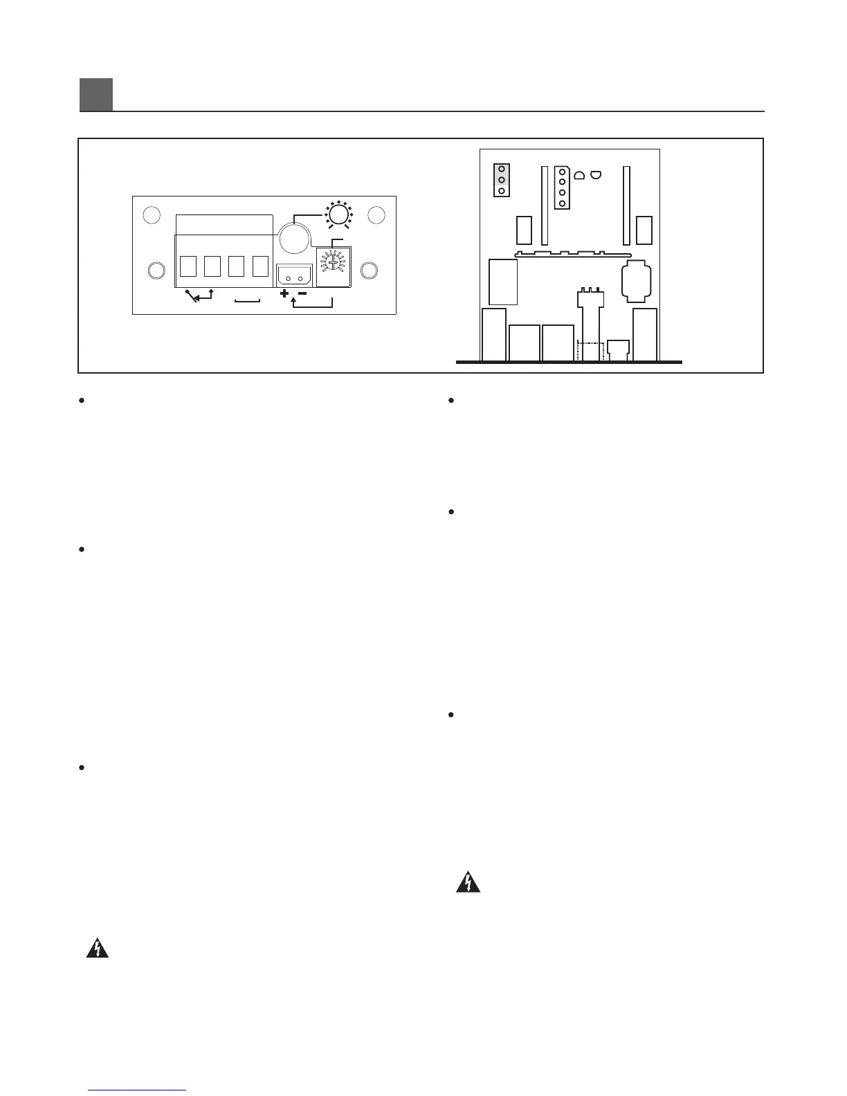
AULT DETECTION MODULE (FD-200)
11
Fault Detector
OSC Level
Sensitivity
min
max
FD-200
HOT
0 10
COM
RMS 2Vac
Test
Line In
VR602
SW1
OSC
CN601
U601U602
Q601
Q602
HIC601
BK1
T601
BK2
RY601
TB2 TB1
XT602 XT601
On
Off
VR601
CN602
(The FD-200 is installed is DPT amplifier.)
(DPT는기본장착임.)
 Loading...