Do you have a question about the Jensen A222HLX and is the answer not in the manual?
| peak power output | 250 Watts |
|---|---|
| power requirement | 14.4 VDC |
| fuse requirements | 25 amp blade-type fuse |
| frequency response | 10 Hz-30kHz ±3 dB |
|---|---|
| signal to noise ratio | >80 dB |
| channel separation | >65 dB, 1 kHz |
| speaker impedance | 2-8 ohms |
|---|---|
| input impedance low level | 10 k ohms |
| input impedance high level | 27 ohms |
| width | 9.25" |
|---|---|
| height | 5" |
| depth | 7.6" |
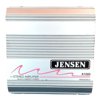
Explains the benefits of using the A222HLX amplifier for improved sound quality and loudness.
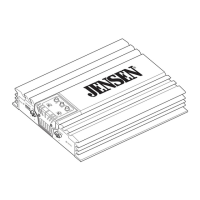
Details suitable mounting locations for the amplifier and the importance of proper ventilation.
Guides on choosing compatible speakers to maximize performance with the A222HLX.
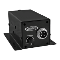
Adjusts the amplifier's sensitivity to match the audio source's output level for optimal signal.
Allows for crossover frequency adjustment to tailor audio output for different speaker types or systems.
Connects the amplifier's output channels to the vehicle's speakers.
Connects the amplifier to the source unit using RCA cables for superior audio input.
Provides an alternative input method using speaker-level outputs from the source unit.
Essential connection to the vehicle's chassis for a safe and effective ground.
Direct connection to the vehicle's battery for a stable power supply.
An indicator light showing that the amplifier is receiving power.
Enables automatic turn-on/off of the amplifier with the car stereo.
Specifies the required fuse type and rating for unit protection.
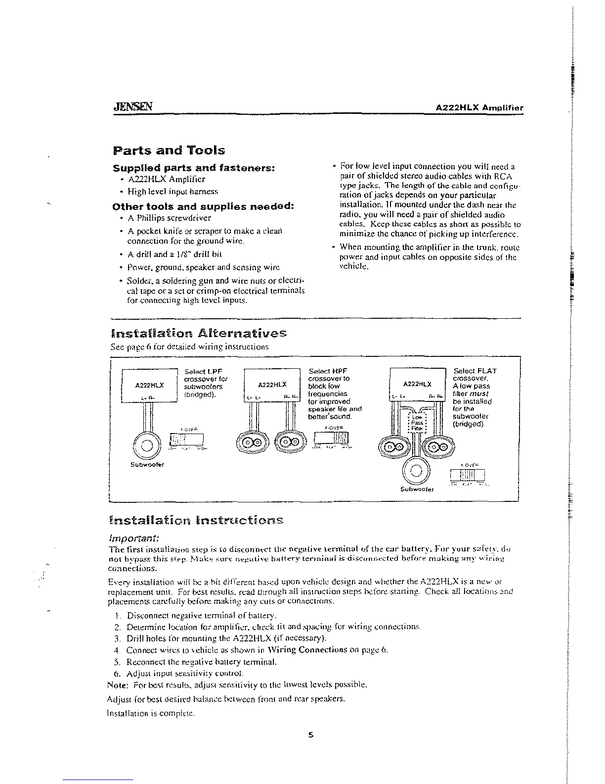
Lists all components and hardware included in the amplifier's packaging.
Details the necessary tools and materials required for a successful installation.
Guides on setting the Low Pass Filter for subwoofer integration, especially in bridged mode.
Explains using the High Pass Filter to protect speakers and enhance sound quality.
Configuration option for bypassing the internal crossover filtering.
Explains how to connect either high-level or low-level audio inputs, but not both simultaneously.
Illustrates how to connect the amplifier's input signals and power to the car's radio system.
Details the proper grounding for high-level input connections to prevent noise.
Shows how to connect the amplifier's speaker outputs to the left, right, and subwoofer.
Emphasizes the critical need for a low pass filter when connecting subwoofers to prevent damage.
Reinforces the importance of a secure chassis ground connection for amplifier operation.
Explains connecting the sensing wire to the power antenna lead or switched ignition source.
Details the direct connection to the vehicle's battery with proper gauge wire.
Addresses issues where the power LED is not illuminated when the system is on.
Solutions for when the radio volume needs to be excessively high for the amplifier to function.
Guidance for when the radio volume is too sensitive or loud.
Troubleshooting steps for audio only coming from one speaker.
Explains how to resolve distorted audio output from the amplifier.
Common causes and fixes for the amplifier repeatedly blowing fuses.
Techniques to eliminate or reduce ignition noise or whine in audio outputs.
How to fix loud popping sounds when turning the amplifier on or off.
Addresses situations where the amplifier shuts down, often due to heat or protection.
Troubleshooting for insufficient or no audio output when using bridged configuration.
General steps for diagnosing and resolving a complete lack of audio output.
Advice on contacting technical assistance for unresolved troubleshooting issues.
Detailed technical data including power output, frequency response, and impedance.
Outlines the warranty period, what is covered, and who is protected.
Instructions on how to get the product serviced under warranty.
Details exclusions, limitations on implied warranties, and consequential damages.