Installation Sheets Manual 121
Temperature Controls Section
Technical Bulletin A19BAC, A28AA
Issue Date 0588
© 1988 Johnson Controls, Inc.
1
Code No. LIT-121077
A19BAC, A28AA Single and Two-Stage Space Thermostats
For Farm and General Purpose Applications
Application
The single-stage A19BAC and
the two-stage A28AA
thermostats incorporate single-
pole double-throw switches for
controlling automatic ventilation
or heating in livestock barns,
poultry houses, milk houses,
brooder houses and other
buildings. The 30 to 110°F (0 to
43°C) and 0 to 140°F (-15 to
60°C) temperature ranges
permit use for many space
applications.
All Series A19 and A28 space
thermostats are designed for
use
only
as operating
controls. Where an operating
control failure would result in
personal injury and/or loss of
property, it is the
responsibility of the installer
to add devices (safety, limit
controls) or systems (alarm,
supervisory systems) that
protect against, or warn of,
control failure.
Operation
On a temperature increase to
the dial setting, the circuit
between R and Y closes.
Simultaneously the R and B
circuit opens.
Figure 3 illustrates the operation
of the A28AA. On a temperature
increase to the dial setting, the
circuit between R and Y of the
low stage switch (RY
L
) closes.
Simultaneously the circuit
between R and B (RB
L
) opens.
On a further increase in
temperature the high stage
switch operates and closes RY
H
while simultaneously opening
RB
H
. The reverse sequencing
takes place on a temperature
fall.
Installation
Mounting
Mounting may be by wiring
conduit or to a flat surface with
screws through holes provided
in back of frame.
!
CAUTION: On rough
mounting surfaces use the
top two mounting holes
only. When these controls
are mounted on an uneven
surface using screws in all
four holes, the case can be
twisted enough to affect
the thermostat’s calibration
and operation.
Mount the thermostat 5 to 6 feet
above the floor where it will be
exposed to the average
temperature of the controlled
space. Do not mount where it
will be affected by unusual heat
or cold, such as directly over an
animal stall or in sunlight. Avoid
locations near a door, window or
hay chute. Do not mount on an
outside wall or where maximum
ambient temperature exceeds
140°F (60°C).
!
CAUTION: Do not dent or
deform the sensitive bulb
of this thermostat. A dent
or deformation will change
the calibration and cause
the thermostat to cycle at a
temperature lower than the
dial setting.
Adjustment
Knob adjustment or screwdriver
slot is supplied on the range
screw. Dial pointer is located on
cutout stop bracket on knob and
screwdriver adjustment models.
Solid cover models are adjusted
by removing cover and moving
dial so set point is in line with
dial pointer on the stop bracket.
(See Fig. 4.)
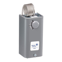
Fig. 1 -- Exterior view of Space
Thermostat.
Convertible adjustment models
can be field converted from
concealed screwdriver slot
adjustment to knob adjustment
or external screwdriver slot
adjustment. They are supplied
with a snap-in plug in the cover
to provide concealed
screwdriver slot adjustment. For
knob adjustment remove the
snap-in plug and press the knob
onto the slotted shaft. For
external screwdriver slot
adjustment remove the snap-in
plug.
The A28AA switch is stamped to
indicate the HI-TEMP switch and
the LO-TEMP switch.
A high temperature cutout stop
is supplied on the thermostats.
(See Fig. 4.) If cutout stop is
required proceed as follows:
1. Set dial to temperature at
which stop is desired.
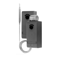
Fig. 2 -- The Space Thermostats
with convertible adjustment
have a snap-in plug in the
cover, built-in screwdriver slot
and a knob for field installation.