Electrical Ratings
A28AA* A19BAC
Volts, AC 120 208 240 277 120 208 240 277
Full Load Amp
16.0 9.2 8.0 -- 16.0 9.2 8.0 --
Locked Rotor Amp
96.0 55.2 48.0 -- 96.0 55.2 48.0 --
Non-Inductive Amp
16.0 9.2 8.0 7.2 16.0 16.0 16.0 16.0
SPDT
SPST
16.0 9.2 8.0 7.2 22.0 22.0 22.0 22.0
Pilot Duty
125 VA, 24 to 277 VAC 125VA, 24 to 600 VAC
* Max connected load not to exceed 2000 VA.
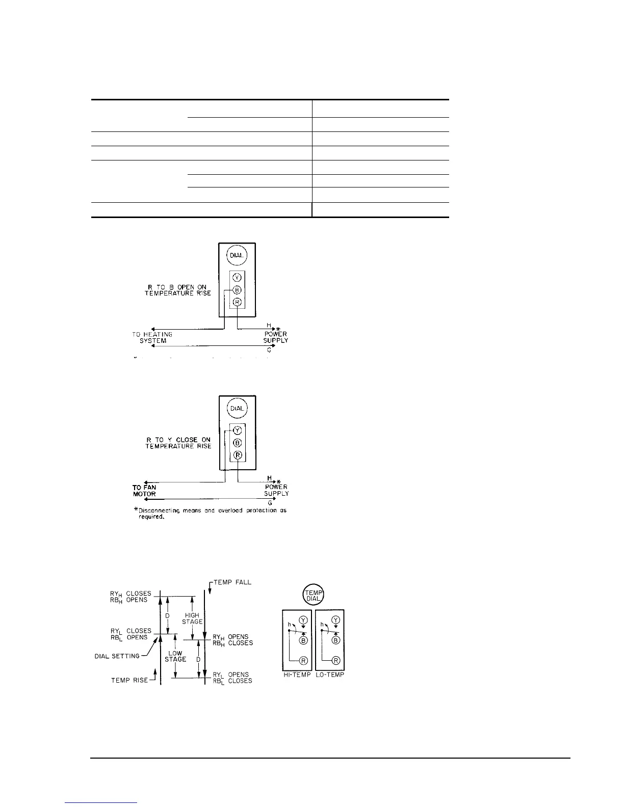
*Disconnecting means and overload protection as required.
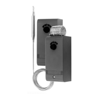
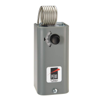
Fig. 4 – A19BAC typical heating control circuit.
Fig. 5 – A19BAC typical ventilating or cooling control circuit.
Fig. 6 – Switch action of the A28AA two-stage control.
RB
H
, RY
H
indicate HI-TEMP. RB
L
, RY
L
indicate LO-TEMP. D
is the differential between stages.
A19BAC, A28AA Installation Instructions 3
 Loading...