T25 Two-Stage Room Thermostat Installation Instructions 3
Make all wiring connections to the screw terminals on
the Pennswitches.
• Use the terminal screws supplied with the
Pennswitches. Screws longer than 1/4 in. can
cause problems in making proper connections.
• Connect the thermostat grounding provision to the
grounding conductor of the branch circuit.
Refer to Figure 4, Figure 5, Figure 6, Figure 7, and
Figure 8 for typical wiring diagrams.
Note: Use the furnished terminal screws
(8-32 by 1/4 in. binder head). Substitution of other
screws may cause problems in making proper
connections.
LL
LO -Temp
Stage
Y
B
h
R
HI-Temp
Stage
Y
B
h
R
Temperature
Dial
Temperature
Fall
H
H
RY Opens
L
RB Closes
Low
Stage
D
Temperature
Rise
Dial
Settings
RY Closes
RB Opens
H
RY Closes
L
RB Opens
D
High
Stage
Note: RB , RY indicates
HI-TEMP. RB , RY indicates
LO-TEMP. D represents differential
between stages. H represents High.
L represents Low.
H
H
H
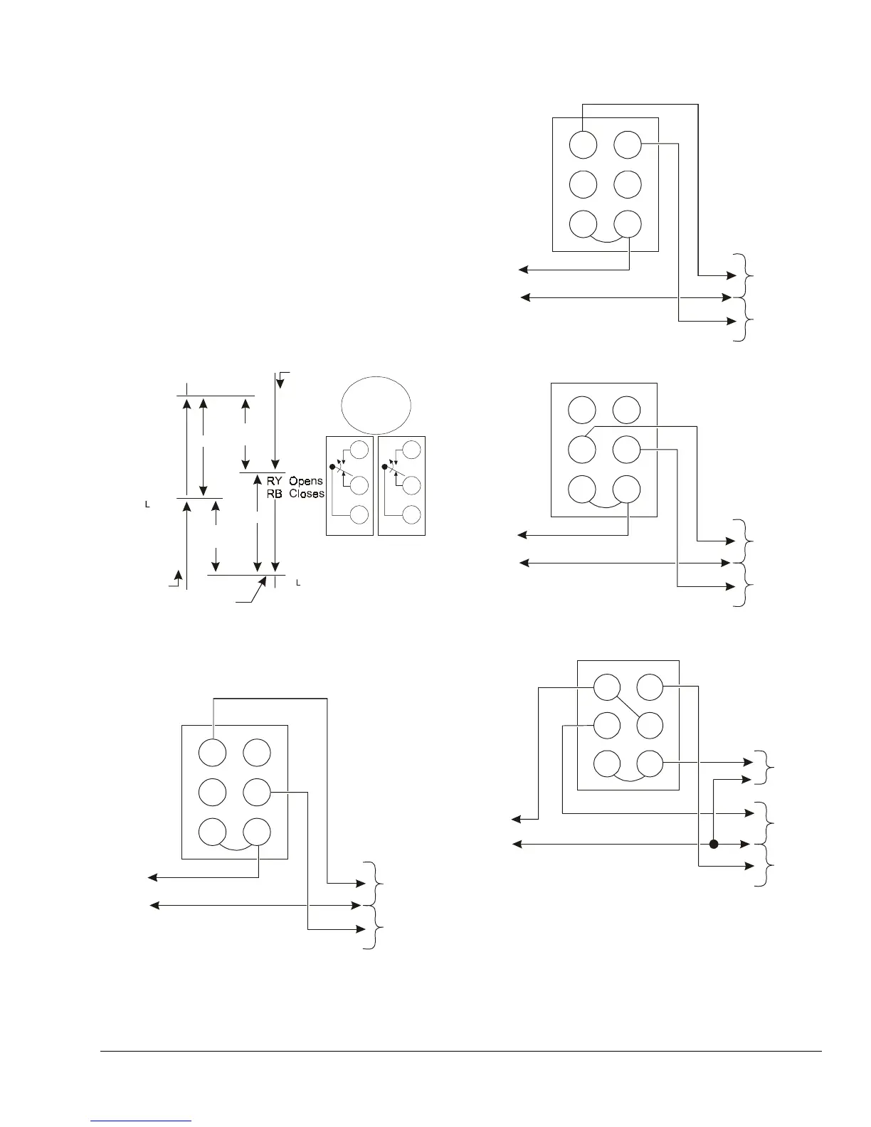
Figure 3: Two-stage Control Switching Action
Hot
Hot
or
Neutral
Power Supply
Cooling
Equipment
Heating
Equipment
Hot (240 VAC)
or Neutral (120 VAC)
Y
H
Y
L
B
H
B
L
R
H
R
L
Figure 4: Typical Wiring for One-stage Heating and
One-stage Cooling
Hot
Hot
or
Neutral
Power Supply
2nd Stage
Cooling
Hot (240 VAC)
or Neutral (120 VAC)
1st Stage
Cooling
Y
H
Y
L
B
H
B
L
R
H
R
L
Figure 5: Typical Wiring for Two-stage Cooling
Hot
Hot
or
Neutral
Power Supply
To
1st Stage
Heating
To
2nd Stage
Heating
Hot (240 VAC)
or Neutral (120 VAC)
Y
H
Y
L
B
H
B
L
R
H
R
L
Figure 6: Typical Wiring for Two-stage Heating
Hot
Hot
or
Neutral
Power Supply
Heating
Valve
Hot (240 VAC)
or Neutral (120 VAC)
Cooling
Valve
Fan
HI-Temp LO -Temp
Y
H
Y
L
B
H
B
L
R
H
R
L
Note: The application is wired for simultaneous cycling of
valve and fan. Cooling will operate at a higher
temperature than heating even though connections
are to opposite stages.
Figure 7: Typical Wiring for Fully Automatic
Heating and Cooling Service
 Loading...