601V-B01A-NB Rev 2-Issue Date 09 2012
1
T6634-TA10҈TE20҈TF20-9JS0 Series Fan Coil Thermostat (ON/OFF) - Installation Instructions
T6634-TA10҈TE20҈TF20-9JS0亨⏄橻㣧䢅䵎㿖㕔⠕ (キ⌠⤸) -ⴶ婲嶡㞻
Field Cabling
⦄എ㒓
Wall Box 2 MX5
Mounting Screw
㺙㒓Ⲧ, ϸᵮMX5
ᅝ㺙㶎䩝
Retention Screw
ᅮ㶎ϱ
ĀWaferā Connector with 12cm 20AWG PVC Cable
ᏺ᳝12cm㒓䭓, ᦦᢨᓣ"Wafer"㒓, 20AWG PVCᓣ⬉㒓
Wall Box
㺙㒓Ⲧ
Base
ᑩⲪ
Cover
1
:
T6634ᇛ༮Ꮝࠞധ࣏ၫ૿ධ
Figure
1
:
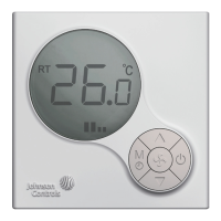
T6634 LCD Digital Fan Coil Thermostat
Application
T6000 LCD Digital Fan Coil Thermostats
The T6000 Digital Fan Coil Thermostats feature local temperature control within fan coil
operations. Select the temperature scale and setpoint, the mode, and the differential values
to control the Heating, Ventilating, and Air Conditioning (HVAC) system that maintains the
desired room temperature. The optional Occupied/Unoccupied feature saves energy by
enlarging the acceptable temperature range.
T6000 features with Backlit Liquid Crystal Display (LCD), one Mode/Timer (
M
/
) selection
button, two Adjustment buttons (ɘ&
), one Fan Speed ( ) selection button and one On/Off
(
) button.
2
:
T6634Ⴜளၫ૿ධڞ܄(mm)
Figure
2
:
T6634 Series Thermostat Dimensions (mm)
Ҿጎ
T6000ၫ૿ධᎧቂ๒ᇸ࣎ൺಸݲၫޡົށݞܿݓߴȃၫ૿ධၤ
ܗװ߶ৱᏓ࿒ၫޡܿݓߴȃןಁၫ૿ධᎧ୩ኑࡒˈࠞଁȂৠ
ධȂ༃ိডᆷࣕጐືܸܿݓߴȃ
Ҿጎ
T6000Ⴜளၫ૿ධົၓᎳ75x75x 35mmුᎧღՙᎧȃ (
3
)
ՙጐፑݒᏰˈնྋᎧුຢღȃ
ጀᅪ
:
ྈT6000Ⴜளၫ૿ධᄲˈᅍᇋౕMx5Ꭷఞݽ (፩Ꮛܕˈᇦ໘ˈᅍت
ቂPWT2.5X5X5.5ఞݽ)ȃ
Installation
Install the T6000 where the occupant can read the display and adjust the setpoint easily.
Situate the thermostat where the temperature is representative of the general room
conditions. Avoid installing the T6000 near cold or warm air drafts, radiant heat, on an
outside wall, or in direct sunlight.
Mounting
Mount the T6000 Series thermostat to a 75x75x35mm standard electrical wallbox. (See
Figure
3
)
Follow the instruction in removing the base and then proceed to the wall box Mounting and
the Wiring sections.
Note:
All T6000 Series models require two No. Mx5 mounting screws (Included in the box,
screw PWT2.5X5X5.5 is required if missing).
ᆌᆩ
T6000ᇛ༮Ꮝࠞധ࣏ၫ૿ධ
T6000༮Ꮝࠞധ࣏ၫ૿ධቂო٠ၫޡହ૿፟ࠞധ࣏ܿතˈቂܾܸ༗
ܿȃࣰᅤዎঽົށၫޡȂࠞཨȂከᄵಠྈᅍد༮ˈହ૿፟ৠȂࠞ
ૼݲ˄HVAC˅Ⴜˈ۰ߑၕڕܿ୲ჲၫޡȃዓৠเ/ႇเ৭૿Ꭷˈතވเ
/ႇเಠၫޡධႇเົށၫޡᏋވקڈၫޡˈ۰ߑ܌ܸኙኑȃ
T6000ၫ૿ධົܕֶࣕᇛმ˄LCD˅Ȃᇜࢋಠ/ৱ˄
M
/
˅ᅤዎՙഀˈߗࢋ
ݲՙഀ˄
ɘ
˅Ȃᇜࢋࠞཨ˄ ˅ᅤዎՙഀᇜࢋOn/Off˄ ˅
601V-B01A-NB Rev 2-Issue Date 09 2012
This document is subject to change without notice 㣙㜴㨐⬯㢶▅Ⓝ的㈂Ὰ▓姹懇䦒
3
:
ّဇ
Figure
3
:
Exploded View
ٶڹӱ
མ˄ᇋถ˅ၫ૿ධݾؠᇜࢋఞݽˈჹଲၫ૿ධˈၫ૿ධܿᇈࢦખ۰
ᎧݒᏰݒؠܿᇈؼလ୰ˈܾᎧღ߾٢ߴצȃሠ፟ݢ௸֊˄PCB˅ࢿށළ
ܿ୴ಅˈಅ፩ؠၓஏݽȃ
Removing the Base
Loosen (Do Not Remove) the single Phillips-Head retaining screw at the top of the case to
swing the thermostat slightly away from the base. By gently sliding it forward, the thermostat
hinge hooks come away from the hinge slots at the bottom of the mounting base to provide
easy access for mounting and wiring. The Printed Circuit Board (PCB) is attached inside the
cover with connection pin near the middle of the mounting base.
70mm.
70mm.
2
7
m
m
.
30mm.
Retention Screw ᅮ㶎ϱ
Hinge Hook
࣒