T6634-TA10҈TE20҈TF20-9JS0 Series Fan Coil Thermostat (ON/OFF) - Installation Instructions
T6634-TA10҈TE20҈TF20-9JS0亨⏄橻㣧䢅䵎㿖㕔⠕ (キ⌠⤸) -ⴶ婲嶡㞻
601V-B01A-NB Rev 2-Issue Date 09 2012
2
4
:
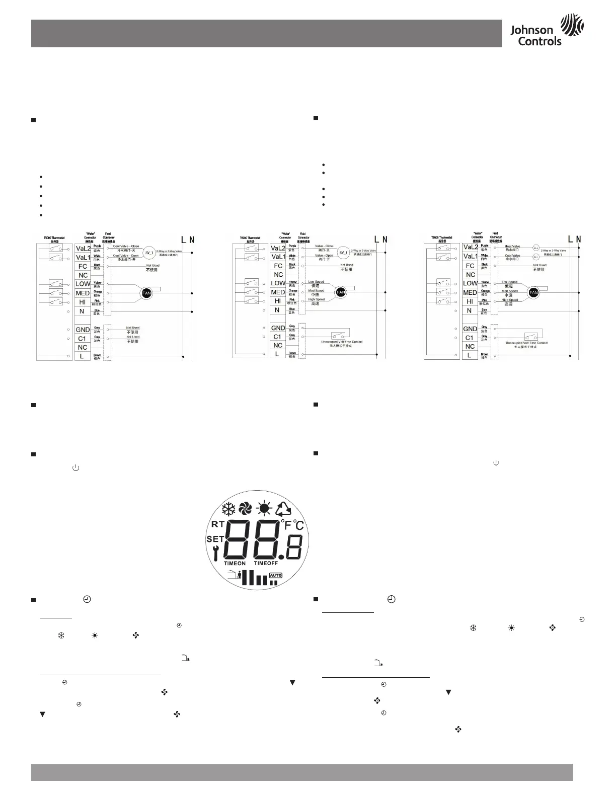
T6634-TA10-9JS0ღဇ
Figure
4
:
Wiring Diagram for T6634-TA10-9JS0
Wallbox Mounting
To mount the T6000 Series Thermostat:
Pull the external field wiring from the wall through the rectangular opening in the base.
Fasten the base to the wallbox using the appropriate two holes and two Mx5 screws, as
shown in
Figure
2
.
Proceed to the Wiring section for the correct configuration for the application and units.
Wiring
Wire the unit according to the instructions for the appropriate model.
Note:
When wiring the T6000 Series Digital Fan Coil Thermostat, use wire nuts to finish and
isolate each connection.
When the wiring is Completed:
Push the connected wiring through the rectangular hole in the base into the wallbox space.
Hook the thermostat to the hinge at the bottom of the base and gently slide the thermostat
down into position on the mounting base.
Tighten the retention screw.
Proceed to the Setup and Adjustment section to establish the desired settings.
Wiring terminal designations and connections for typical applications appeared in
Figure
4
-
6
.
഻ጎ࢈Ҿጎ
ᎧT6000Ⴜளၫ૿ධ:
նိؠღ۰ු୴ଲڵࣰܿߴᄳݒᏰȃ
ࣰࢋᎧ૾ቪౕMx5ఞݽˈնݒᏰࢿށᎧຢˈ
2
ྈȃ
ࢎદሥቂٛ൰ܿᇋชᄵጸฬܿღȃ
থ၍
ࢎદፑܷˈࢍܬᄲܿၫ૿ධღȃ
ጀᅪǖ
ࢍT6000Ⴜள༮Ꮝࠞധ࣏ၫ૿ධღˈቂღఞဵڈુኒࢋ
ღޤȃ
ړথ၍ྜׯࢫ
:
ࣰݒᏰߴᄳ૾ˈնஏღထුᎧ୴ȃ
ݒᏰᇈۃնၫ૿ධࢦ᎘ထވၫ૿ධፚᎧݒᏰຢಅȃ
ࢿށམఞཎȃ
ՙົށݲົށჲᇋܿد༮ȃ
ࢎદ
4
-
6
ܿݟᄲሥቂˈࢍፑށღޤღȃ
7
:
T6000 LCDმ
Figure
7
:
T6000 LCD Display Pattern
ֱօየ
ၫ૿ධᎧဵגˈ୰ፇᇋ৹ي፟୩ৠဵጶܿغᏮᅰȃጝᆼ૰ᇵฬ֦
ྈ૿፟ົֻ࢙ጸ٢ȃ࣮ღጸฬˈߑົֻቕጸ٢ᏮˈขખႼ
JohnsonControls
®
֑ۃହ࿓ၫ૿ධȃ
ยዃࢅۙব
ՙOn/Off ( ) ՙഀˈත࣋טT6000ၫ૿ධȃT6000ၫ૿ධᇵˈၫ૿ධმ
ၫޡȃLCDმဇˈ˄
7
˅ȃ
دૣװ2ˈT6000Ⴜளၫ૿ධڵ٦ົށፎ
Check-Out Procedure
After the installation, observe the complete operation cycles for cooling and heating control.
This is to make sure that all control devices are functioning correctly. If the device is not
working properly and the wiring is correct, the thermostat should be replaced by contacting
your nearest Johnson Controls
®
Representative.
Setup and Adjustments
Turn ON/OFF the T6000 Thermostat by pressing the On/Off ( ) button. After turning on
the T6000 Thermostat, ambient temperature will be displayed. LCD displays the icons. (see
Figure
7
).
The T6000 Series Thermostat comes with the default settings specified in Table 2.
֡ፕ
- M/
Ӏ౧
ఇ๕֡ፕ
T6634ၫ૿ධˈ፯ಠᅤዎװ1ȃՙ
M
/ ՙഀغᏮၫ૿ධˈൺಸຢঐՙགᅗڵო
፟୩ (
)Ȃ፟ ( )Ȃࠞ ( )˄T6634-TA10-9JS0ႇ፟ಠ˅ȃ־ᅤܿಠဇ
ດཇˈ3SᏋވฬไဇ־ᅤށȃᅤށဇດཇˈጸ٢მൺಸຢȃ
Ꭷமเ/ႇเ৭૿Ꭷˈเ/ႇเಠ ( ) ঐතވȃ
้ࠀీഔࢅ้ࠀీ࠲Կ֡ፕ
ՙ
M
/ 3ಊށ࢙ົȃۨ
TIMEON
ဇڵოˈດཇˈቂɘ
ົށށৱ˄0~24ᄆ߭ၐ˅ՙ
ᄵฬไȃ
۫ՙ
M
/
ށ࣋ಠົށˈۨ
TIMEOFF
ဇڵოˈດཇˈቂɘ
ົށށ࣋ৱ˄0~24ᄆ߭ၐ˅ՙ ᄵฬไȃ
࣮3-5ಊౚ༕ˈൺಸ߬ইმၫޡȃ
Operation - M/ Button
Mode Operation
On the T6634 series, three modes are available as shown in Table 1 . Short press of the
M
/
button switches through the sequence of Cooling (
), Heating ( ), Fan only ( ) modes
followed by operation (No Heating mode for T6634-TA10-9JS0). The selected icon will
flash, the icon is selected after 3 seconds. The selected icon appears highlighted on the
LCD.
Unoccupied mode (
), will only be activated when the Occupied/Unoccupied contact is wired.
Time-On and Time-Off Operation
Holding down the
M
/ button for 3 seconds will enter the Timer On-Off setting. When the
TIMEON
icon appear and flash, use ɘ and
keys to set the time duration (0 ~24 -Hours
Range). Press key
to confirm the settings.
Holding down the
M
/
button for seconds will enter the Timer On-Off setting, additional one
press to enter Time-On setting. When
TIMEOFF
icon appears, use ɘ and keys to set the
time duration (0 ~ 24-Hours Range). Press key
to confirm the settings.
Note:
The thermostat returns to the default screen if no entry occurs within 3 -5seconds.
5
:
T6634-TE20-9JS0ღဇ
Figure
5
:
Wiring Diagram for T6634-TE20-9JS0
6
:
T6634-TF20-9JS0ღဇ
Figure
6
:
Wiring Diagram for T6634-TF20-9JS0
 Loading...