TEC22x6(H)-4 and TEC22x6H-4+PIR Series LONWORKS® Network Thermostat Controllers with
Dehumidification Capability, Fan Control, and Occupancy Sensing Capability Installation Instructions
7
Connecting the LONWORKS Network
The wiring rules for the LONWORKS network differ from
the wiring rules for the Metasys® N2 Bus and the
BACnet® Master-Slave/Token-Passing (MS/TP) Bus.
For more details on wiring the L
ONWORKS network,
refer to the L
ONWORKS Network Layout Technical
Bulletin (LIT-1162150).
To connect the thermostat to the L
ONWORKS network:
1. Connect the L
ONWORKS network wires to the
L
ONWORKS network terminal block on the
thermostat (Figure 5 and Figure 6).
Note: There is no polarity when connecting the
L
ONWORKS network wires to the thermostat;
however, we recommend keeping the polarity
consistent throughout the network.
2. After the L
ONWORKS network wires are connected
to the first thermostat, continue in a daisy-chained
fashion to the next device.
Note: The L
ONWORKS network wiring must be
twisted-pair lines.
Do not run the L
ONWORKS network wiring in the same
conduit as line voltage wiring (higher than 30 VAC) or
other wiring that switches power to highly inductive
loads (such as contactors, coils, motors, or
generators).
The L
ONWORKS network requires proper termination
and biasing at the end of a segment (a segment is a
physically continuous length of wire). The thermostat is
not equipped with the ability to provide this termination;
therefore, it cannot be located at the physical end of a
L
ONWORKS network segment unless a terminator is
attached. Refer to L
ONWORKS Network Layout
Technical Bulletin (LIT-1162150) for end-of-line
solutions.
Setup and Adjustments
Thermostat User Interface Keys
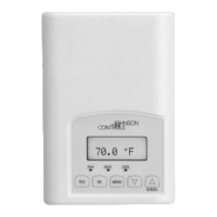
The TEC22x6(H)-4 and TEC22x6H-4+PIR Series
Thermostat UI consists of five keys on the front cover
(Figure 11). The function of each key is as follows:
• MODE key toggles among the system modes
available, as defined by selecting the appropriate
operation sequence in the Installer Configuration
Menu (Off, Heat, Cool, Auto).
• FAN key toggles among the fan modes available,
as defined by selecting the appropriate fan menu
options defined in the Installer Configuration Menu
(Low, Med, High, Auto).
• OVERRIDE key (commercial models) overrides
the unoccupied mode to occupied at the local user
interface for the specified TOccTime. (TOccTime is
defined by selecting the appropriate time period in
the Installation Configuration Menu.) If one of the
binary inputs is configured to operate as a remote
override contact, this OVERRIDE function is
disabled. The OVERRIDE key also allows access
to the Installer Configuration Menu. See the
Configuring the TEC22x6(H)-4 and
TEC22x6H-4+PIR Series Thermostat Controllers
section.
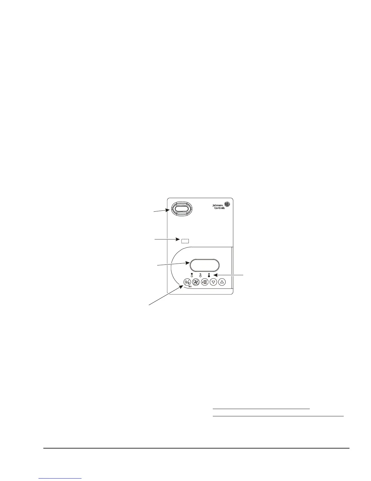
Figure 11: Front Cover of Thermostat Controller (TEC22x6H-4+PIR Model Shown)
Room Temp
frntvw
Status LED beneath cover
indicates network status.
Five keys on the thermostat controller
make operation easy and intuitive.
Backlit, plain text
Liquid Crystal Display (LCD)
is easy to read in any condition.
Light-Emitting Diodes (LEDs)
indicate system activity.
PIR motion detector
saves energy using
standby setpoints.
 Loading...