OPERATING MANUAL for
BRAKE UNITS
JB10/... JB16/... JB26/... JB40/... JB52/...
(Installation set)
JB
7 of 19
01.96/00/Scho
7 INSTALLATION
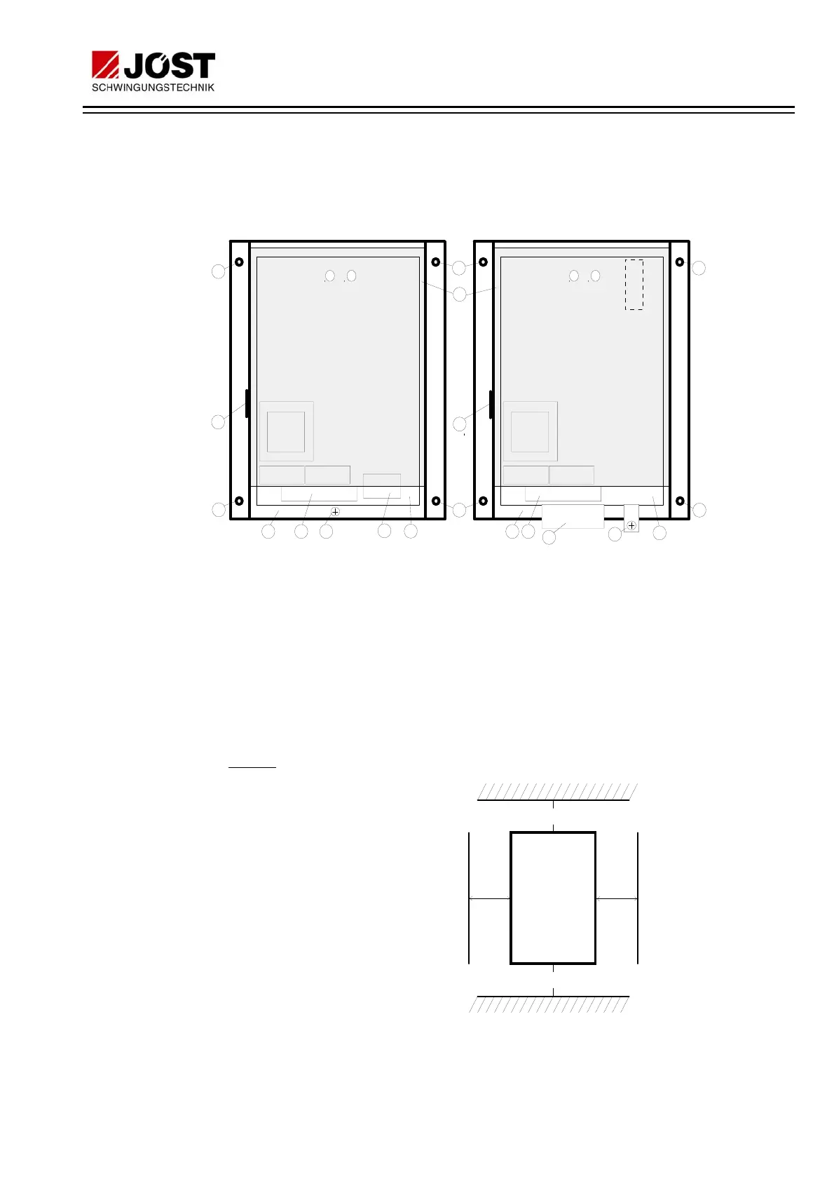
7.1 CONSTRUCTION
The major components of JB brake units are as follows:
6
6
5
4
1
2
PE
6
6
3
7
8
4 2
6
6
5
7
3
JB10/...E000
JB16/...E000
JB26/...E000
JB40/...E000
JB52/...E000
PE
Zeit Strom Zeit Strom
8
1. Perspex cover
2. 9-pole connecting terminal X1 for control signals
3. 3-pole connecting terminal X2 for power signals
4. Heatsink with thyristor
5. Rating plate
6. Mounting holes
7. PE connection screw
8. Control board
7.2 NOTES ON INSTALLATION
Cooling
:
The JB brake unit is
cooled by natural con-
vection. In order to
guarantee an adequate
air flow, the equipment
must be mounted up-
right and the minimum
distances shown in the
adjacent illustration ob-
served. The cooling air
must be as clean as
possible and free of ag-
gressive substances.
Should the cooling air
contain dust, the cooled
areas must be cleaned regularly.
JB -
Brake
100 mm
100 mm
unit
50
mm
50
mm
 Loading...