– 13 –
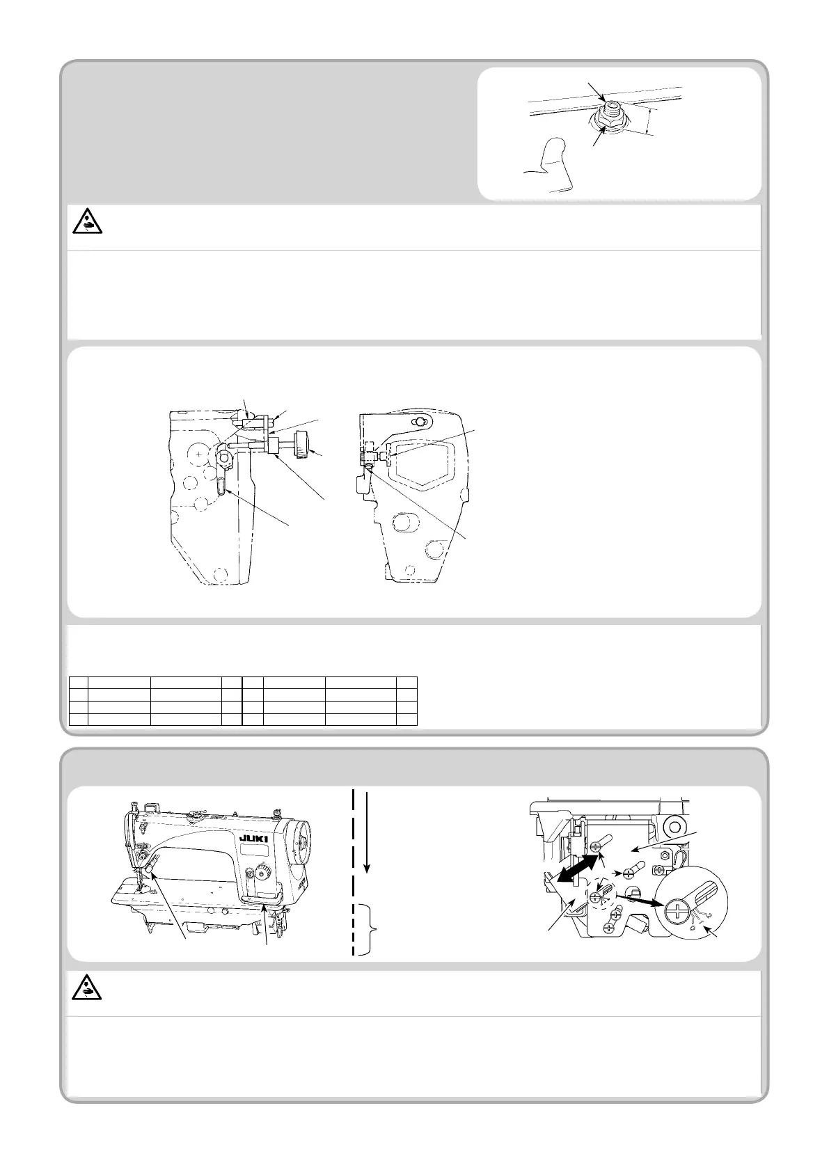
26. MICRO-LIFTING MECHANISM OF THE PRESSER FOOT
For DDL-9000B, the presser foot micro-lifting mechanism is provided as standard. When it is frequently used, however, it is convenient to use the micro-lifting
device (separately available) which can be adjusted without using tools.
Presser foot micro-lifter components
No. Part No. Description
Q’ty
No. Part No. Description
Q’ty
1 23611106 Hand lifter 1 4
D5119206K0K
Collar 2
2 23610504 Stopper base 1 5 23610702 Nut 1
3 23610652 Stopper screw 1 6
SL6053592TN
Setscrew 1
WARNING :
Turn OFF the power before starting the work so as to prevent accidents caused by abrupt start of the sewing machine.
When sewing velvet or the like which is uffy, slippage of material or damage of material is reduced by using screw
1
for presser foot micro-lifting. Lower the
presser foot and set the state that the feed dog is lower than the throat plate.
Gradually tighten screw
1
for presser foot micro-lifting in the state that nut
2
is loosened, nely adjust the position of the presser foot until it matches the
material, and x it with nut
2
.
(Caution) When the presser foot micro-lifting mechanism is not used, adjust the height of screw
1
so that it is higher by approximately 9 mm than
the sewing machine. If the sewing machine is operated in the state that the micro-lifting mechanism is working, sufcient feed force cannot be
obtained.
Approx. 9 mm
1
2
22908552
Hand lifter cam (mounted on the machine head is used)
B1521555000
Hand lifter setscrew (mounted on the machine head is used)
Presser foot micro-lifter (asm.) [40056622] (Separately available)
WARNING :
Turn OFF the power before starting the work so as to prevent accidents caused by abrupt start of the sewing machine.
It is possible to change the stitch length of the normal feed pitch by operating switch
1
or reverse feed control lever
2
during sewing.
1)
Tilt the machine head, and loosen three xing screws
4
of the reverse feed solenoid
3
.
2) Slide reverse feed solenoid
3
in the direction of the arrow to adjust so that the center of screw
4
is aligned with engraved marker line
5
representing the
condensation stitch length. Then x the solenoid with setscrews
4
.
3)
To return the stitch length back to the initial setting (to reset), slide reverse feed solenoid
3
in the direction of arrow
A
until it comes in contact with the end
face of slit in bed strut B
6
. Then, x the solenoid at that position with setscrews
4
.
Sewing direction
Condensed stitch
27. SEWING CONDENSED STITCHES
1
2
6
3
4
A
5
1
5
3
2
6
4
 Loading...