14
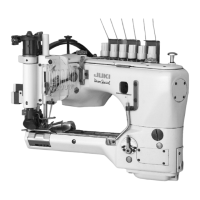
FIG. 14
FIG. 16
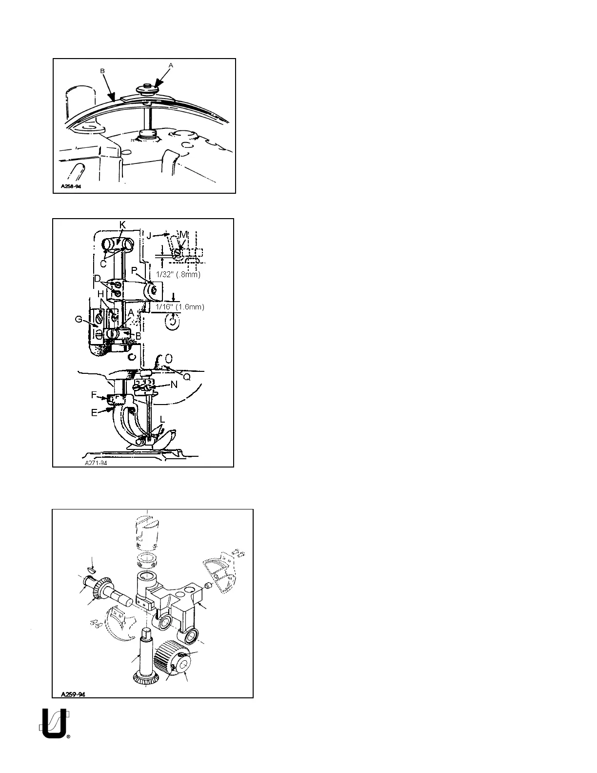
PRESSER FOOT AND PRESSER BAR ADJUSTMENT
Adjusting or Replacing Presser Foot:
Remove presser bar leaf spring (B, Fig. 14) and nut (B). Loosen screw
(A, Fig. 15) on presser bar guide (B). Loosen screws (C) in upper
collar and screws (D) in needle lever thread pull-off lever.. Slide
presser bar upward high enough to slip on presser foot yoke (E) with
foot attached and tighten screw (F) on flat of presser bar. Position
foot so that the needle holes in the foot line up with the holes in the
throat plate. Tighten screw (A)
Presser foot guide plates (G, Fig. 15) should be set so that entire
presser foot and bar assembly has free movement up and down
with no left to right movement.
With foot properly aligned on throat plate and presser bar guide (B,
Fig. 15) securely fastened to presser bar, adjust both guide plates
(G) to obtain above setting. Tighten four screws (H).
Reinstall presser bar spring (B, Fig. 14) and knob (A), with presser foot
resting on throat plate.
Set upper stop collar (K) to contact casting, so the bottom of the
needle head and the top of the presser foot do not touch, at the
bottom of the needle stroke when lifting foot. Tighten screw (C).
The presser foot should be adjusted to be 1/8" (3.17mm) above the
throat plate before the feed roller mechanism begins to rise.. Loosen
screw (A, Fig. 15) in presser bar lifter and guide (B), raise or lower
guide as required to attain the specified point at which the feed
roller begins to rise. Retighten screw (A) and maintain needle
settings.
NOTE: There should be a minimum 1/32" (0.8mm) clearance
between screw (M, Fig. 15) and the bottom of the slot in link
(J).
Regulate the pressure on the presser foot by turning the presser spring
regulating knob (A, Fig. 14) located on top of pressure foot spring (B)..
To remove just the presser foot, remove screws (L, Fig. 15) and replace
foot, retighten screws (L).
Needle lever thread pull-off (P) should be set 1/16 (1.6mm) above
bottom of slot in cover (Q) when presser foot is resting on throat plate.
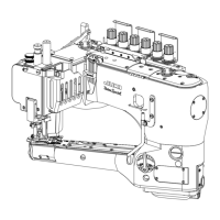
UPPER FEED ROLLER ADJUSTMENT
Assembly of Roller to Roller Yoke:
Assemble driven gear (A, Fig.16) through feed roller frame (B).
Place woodruff key (C) into slot of feed roller shaft (D). Slide
driven gear (E) on to shaft (D), make sure key (C) goes into slot
in gear (E). While holding feed roller frame (B) with steel roller
(F) between the two frame lobs, slide feed roller shaft (D) and
assembled components through frame. Make sure that shoul-
der of roller (F) is to the right. Align screw (G) (first in operating
direction on roller) on the flat of shaft (E). At the same time thrust
shoulder of shaft (D) against face of gear (E), make sure left
edge of roller is against right (inside) face of left lob. Secure
screw (G) on flat of shaft (D) and tighten screw (H).
FIG. 15
E
H
F
G
A
D
C
B
 Loading...