SRX110 Services Gateway Quick Start
The instructions in this guide help you connect the SRX110 Services Gateway to your
network. For details, see the SRX110 Services Gateway Hardware Guide at
http://www.juniper.net/techpubs/a063.html.
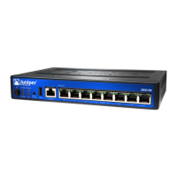
SRX110 Services Gateway Front Panel
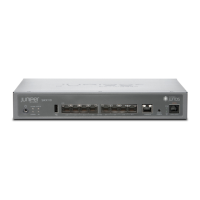
SRX110 Services Gateway (SRX110H-VA) Front Panel
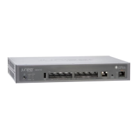
SRX110 Services Gateway (SRX110H-VB) Front Panel
SRX110 Services Gateway Back Panel
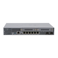
SRX110 Services Gateway (SRX110H-VA and SRX110H-VB) Back Panel
NOTE: If you experience a problem with the CompactFlash card, you must return the
services gateway for repair or replacement. To do this, contact Juniper Networks
Technical Assistance Center (JTAC).
SRX110 Services Gateway Models
The following models of SRX110 Services Gateways are available:
Connecting and Configuring the SRX Series Device
Following are the tasks for connecting and configuring the SRX110 Services Gateway.
The LEDs on the front of the device indicate the status of the device.
Overview
The services gateway requires these basic configuration settings to function properly:
All interfaces must be assigned IP addresses, bound to zones, and configured as
Layer 3 interfaces.
Policies must be configured between zones to permit or deny traffic.
Source NAT rules must be set.
Callout Description Callout Description
1 Power button 5 Console port
2 LEDs: Alarm, Status,
Power, and 3G
6 Reset Config button
3 Universal serial bus (USB)
port
7 LEDs: SYNC and TX/RX
4 Fast Ethernet ports 8 For SRX110H-VA—VDSL/ADSL-POTS
For SRX110H-VB—VDSL/ADSL-ISDN
Callout Description Callout Description
1 Cable tie holder 5 CompactFlash card
2 3G-WAN (USB port) 6 Power supply point
3 Lock 7 Cable tie holder
4 Grounding point
Device DDR Memory
SRX110H-VA (VDSL/ADSL-POTS) 1 GB
SRX110H-VB (VDSL/ADSL-ISDN) 1 GB