b. The cable with very low resistance (indicang a closed circuit) to chassis ground is posive (+) and is installed on
the RTN (return) DC power input terminal.
3. Remove the protecve cover from the DC power input terminal block. Save this cover for future use.
4. Remove the M5 K-nuts from each DC power input terminal.
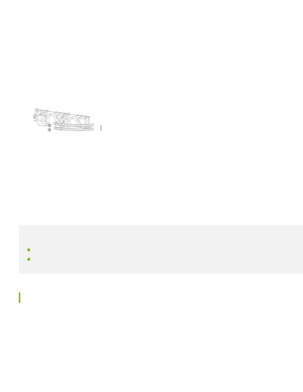
5. Aach DC terminal rings (TYCO 2-36161-2 Terminal Ring, number 10, not provided) to the ends of the DC power
cables. Crimp ghtly.
6. Insert the DC terminal rings into the DC power input terminals and secure the DC terminal rings with M5 K-nuts. Do
not overghten.
7. Replace the protecve cover over the input terminal block.
8. Remove the tape from the switch handle of the circuit breaker on the panel board that services the DC circuit, and
switch the circuit breaker to the ON (|) posion.
9. Verify that the OK/FAIL LED is lit green and on steadily.
Step 2: Up and Running
IN THIS SECTION
Set Parameter Values | 5
Perform the Inial Conguraon | 6
Set Parameter Values
You must perform the inial conguraon of the device through the console port. Before you begin, set the following
parameter values in the console server or the management host:
• Baud Rate—9600
• Flow Control—None
• Data—8
5
 Loading...