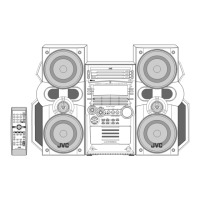
1-12 (No.MB366)
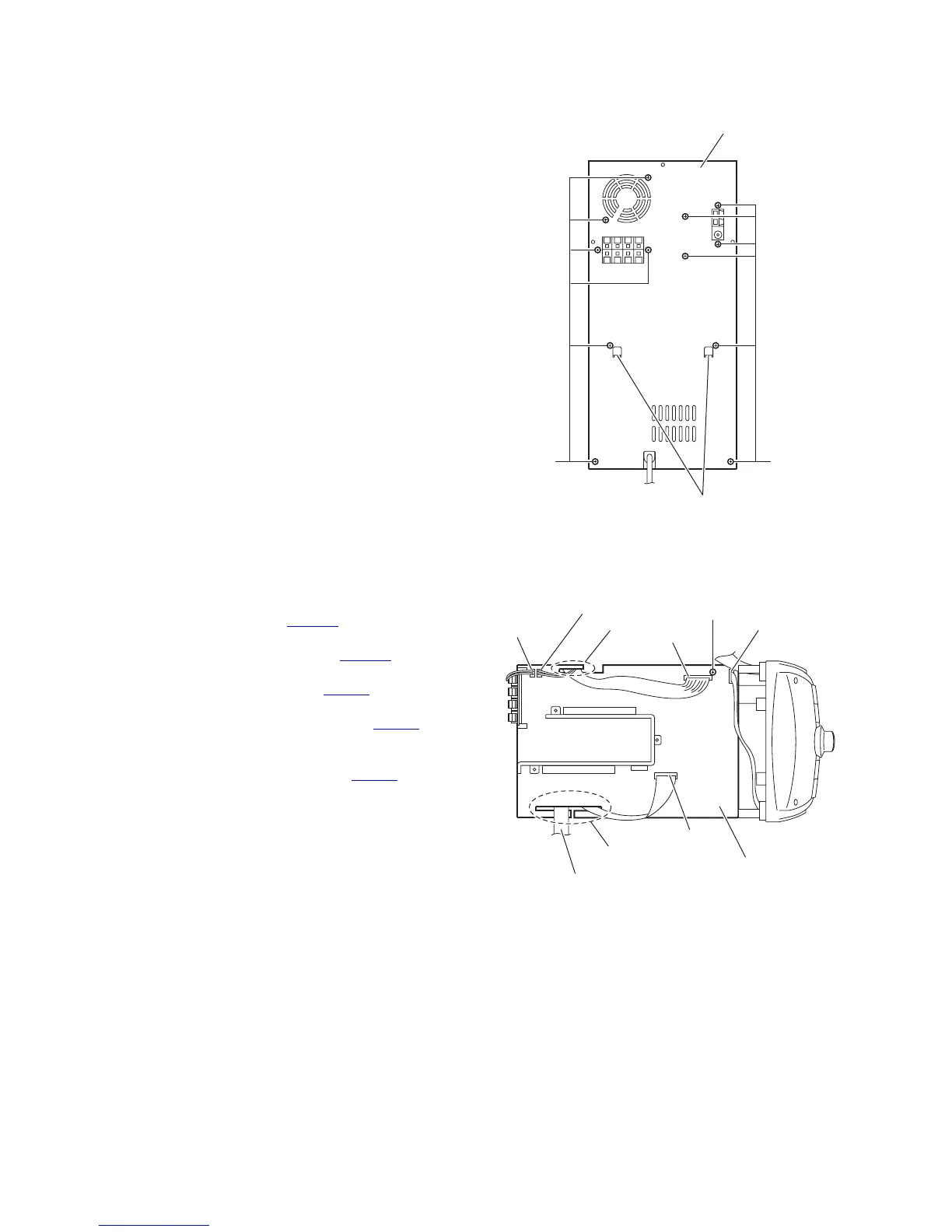
3.1.5 Removing the rear panel
(See Fig.12)
• Remove the metal cover.
(1) From the back side of the main body, remove the twelve
screws F attaching the rear panel.
(2) Remove the sections d toward this side and remove the
rear panel.
Fig.12
3.1.6 Removing the amplifier board
(See Fig.13)
• Remove the metal cover and rear panel.
(1) From the top side of the main body, disconnect the wire of
the fan motor from the connector FAN101
on the amplifier
board.
(2) Disconnect the wire from the connector FAN102 on the
amplifier board and remove the wire from the slot e.
(3) Disconnect the wire from the connector AW102
on the am-
plifier board.
(4) Disconnect the parallel wire from the connector CW108
on
the amplifier board and remove the parallel wire from the
slot e.
(5) Disconnect the card wire from the connector AW101
on the
amplifier board and remove the card wire from the slot f.
(6) Remove the card wire of the tuner from the slot f.
Reference:
• Remove the tuner as required.
• When connecting the each wire, pass them through
the slots (e, f) as before.
(7) Remove the screw G and take out the amplifier board from
the main body.
Fig.13
Rear panel
FF
d
Amplifier board
FAN101
Card wire (for the tuner)
AW101
FAN102
CW108
AW102
G
e
f
 Loading...